
Sprint-Import L3-061 1000cc 1.0L Turbo VIN 2 FI (1987)
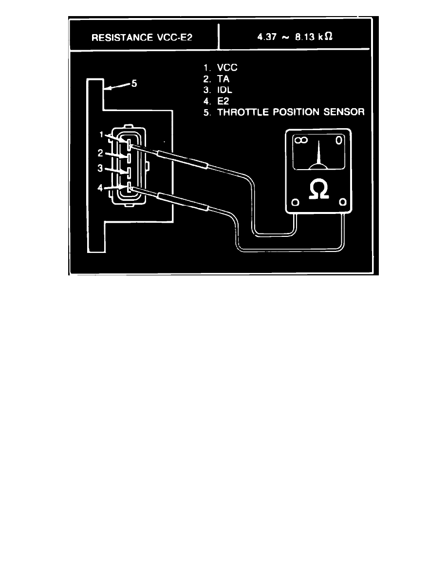
Fig. 12 Checking throttle position sensor (VCC-E2)
1.
Check continuity between VCC-TA and TA-E2. Although a value is given, only a continuity check is necessary, Fig. 11.
2.
Check that throttle lever contacts throttle stopper bolt when when throttle valve is fully closed.
3.
Check for continuity after inserting a .016 inch thick gauge between throttle lever and throttle stopper bolt. Continuity should exist. Continuity
should not exist when a .031 inch thick gauge is inserted. If check is not as specified, adjust installation angle throttle position angle as described
under ``Throttle Position Sensor, Replace'' procedure.
4.
Check resistance of VCC-E2 as described, Fig. 12.