
Suburban 1/2 Ton 2WD V8-5.3L VIN T (2004)
^
If the color of the relief valve is silver or aluminum, continue to the next step.
Important
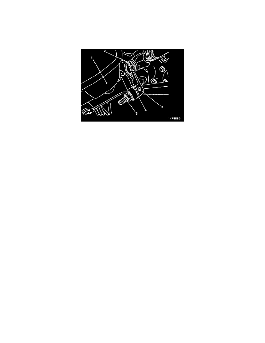
If present, the stamped number being described in the next step would be on the mounting surface for the master cylinder on the hydraulic
brake booster. The number may be difficult to see if there is any corrosion on the unpainted surface. As a result, it may be necessary to clean
the surface with a piece of emery or sandpaper.
3.
Inspect the hydraulic brake booster at the location shown (4) for a stamped number. The location (4) is the same surface that the master cylinder
mounts on, just above the outboard mounting bolt and nut (5). Also inspect for a paint mark (3) near the master cylinder outboard mounting bolt
(5). If a stamped number is found it will be a 1, 2, 3, or 4. If a paint mark is found, it will be yellow, pink, or white.
^
If a yellow, pink, or white paint mark IS visible, no further inspection or repairs are required. Disregard any stamped number found when a
yellow, pink, or white paint mark is visible.
^
If there are NO paint marks and there IS a stamped number 2, 3, or 4 visible, no further inspection or repairs are required.
^
If there are NO paint marks and there IS a stamped number 1 visible, then proceed to the next step.
^
If there are NO paint marks and there are NO stamped numbers visible, then proceed to the next step.
Caution
Care should be taken when working around the accumulator since it contains high-pressure compressed gas and hydraulic fluid.
4.
With the ignition in the OFF position, pump the brake pedal a minimum of ten times.
5.
On van models, remove the two bolts that attach the diagonal brace between the left front fender and radiator support. Remove the brace and the
water deflector that is attached to it.
6.
On all models, remove the two nuts that attach the master cylinder to the hydraulic brake booster. A 13 mm wrench installed on the bolt head may
be required to prevent the bolt from spinning.
Important
On full size pickups and utilities, the bracket that attaches the brake combination valve will need to be removed from the mounting bolts at the
same time that the master cylinder is removed and repositioned in the next step.
Notice
When repositioning the master cylinder in the next step, use care not to pinch, kink, or damage the brake hoses or pipes.
7.
Remove and reposition the master cylinder away from the hydraulic brake booster so that the machined surface on the front of the booster where
the master cylinder was mounted is visible.