
Suburban 1/2 Ton 4WD V8-5.3L VIN Z Flex Fuel (2006)
6. Install the remaining J45101-100 and lug nuts onto the wheel studs and tighten the nuts firmly by hand in a star-pattern.
7. Using the J39544-KIT, or equivalent, tighten the lug nuts in a star-pattern to specification, in order to properly secure the rotor. Refer to Tire and
Wheel Removal and Installation in Tires and Wheels.
8. If the brake rotor has been REFINISHED or REPLACED with a new rotor, proceed to step 14.
9. If the brake rotor meets the following criteria, proceed to step 10.
^
The rotor is within specifications and is being REUSED
^
The rotor has NOT been refinished
^
The rotor does NOT exhibit thickness variation exceeding the maximum allowable level
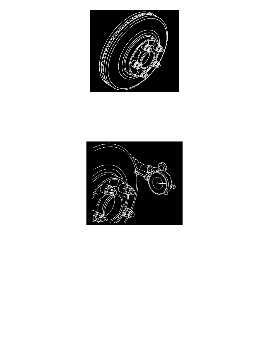
10. Mount a dial indicator, J45101, or equivalent, to the steering knuckle and position the indicator button so it contacts the brake rotor friction
surface at a 90 degree angle, approximately 13 mm (0.5 inch) from the outer edge of the rotor.
11. Measure and record the assembled LRO of the brake rotor.
11.1.
Rotate the rotor until the lowest reading is displayed on the indicator dial, then set the dial to zero.
11.2.
Rotate the rotor until the highest reading is displayed on the dial.
11.3.
Mark the location of the high spot relative to the nearest wheel stud, or studs.
11.4.
Measure and record the amount of LRO.
12. Compare the brake rotor assembled LRO to the following specification:
^
Front brake rotor maximum allowable assembled lateral runout: 0.13 mm (0.005 inch)
^
Rear brake rotor maximum allowable assembled lateral runout: 0.13 mm (0.005 inch)
13. If the brake rotor assembled LRO is within specifications, proceed to step 18.
If the brake rotor assembled LRO exceeds the specification, refinish the rotor to ensure true parallelism, refer to See: Service and Repair/Brake
Rotor Refinishing After refinishing the rotor, proceed to step 14.
14. Mount a dial indicators J45101 or equivalent, to the steering knuckle and position the indicator button so it contacts the brake rotor friction surface
at a 90 degree angle, approximately 13 mm (0.5 inch) from the outer edge of the rotor.
15. Measure and record the assembled LRO of the brake rotor.
15.1.
Rotate the rotor until the lowest reading is displayed on the indicator dial, then set the dial to zero.
15.2.
Rotate the rotor until the highest reading is displayed on the dial.
15.3.
Mark the location of the high spot relative to the nearest wheel stud. or studs
15.4.
Measure and record the amount of LRO.