
Tahoe 2WD V8-6.0L Hybrid (2008)
If a condition is found, clean the area and repair as needed. Refer to Wiring Systems and Power Management > Diagnostic Information and
Procedures in SI.
9. Connect the negative battery cable. Refer to Battery Negative Cable Disconnection and Connection in SI.
10. Clear any DTCs that may be present with a scan tool and verify the proper operation of the vehicle.
Lost Communication With DTC's Set
Lost Communication with Various Control Modules and DTCs Set
DTC Descriptors
Note
Depending on the vehicle there may be other DTCs set by other modules.
-
DTC U0073 Control Module Communication Bus A Off
-
DTC U0100 Lost Communication with Engine/Powertrain Control Module (ECM/PCM)
-
DTC U0101 Lost Communication with Transmission Control Module (TCM)
-
DTC U0102 Lost Communication with Transfer Case Control Module
-
DTC U0121 Lost Communication with Electronic Brake Control Module (EBCM)
-
DTC U0140 Lost Communication with Body Control Module (BCM)
1. Connect a scan tool and perform the Diagnostic System Check - Vehicle. Retrieve and record any existing history or current DTCs from all of the
control modules (refer to SI).
If any DTC(s) are set, refer to the list above or the Diagnostic Trouble Code (DTC) List - Vehicle to identify the connector(s) of the control
module/component which may be causing the condition (refer to SI).
2. Turn OFF the ignition and all accessories.
3. Disconnect the negative battery cable. Refer to Battery Negative Cable Disconnection and Connection in SI.
4. Disconnect the connector(s) at the affected module.
5. Inspect the connector(s) for the following conditions:
-
Backed out terminals
-
Bent pins
-
Corrosion
-
Poor terminal fit (use the correct test probe)
-
Water intrusion
‹› If a condition is found, repair as needed. Refer to Wiring Systems and Power Management > Diagnostic Information and Procedures in SI
AND
‹› If corrosion or water intrusion is found, proceed to the section of the bulletin titled: Repairing Fretting Corrosion to complete the repair.
6. Reconnect the connector(s) at the affected modules.
7. Clear any DTCs that may be present with a scan tool and verify the proper operation of the vehicle.
Repairing Fretting Corrosion
Repairing Fretting Corrosion
Note
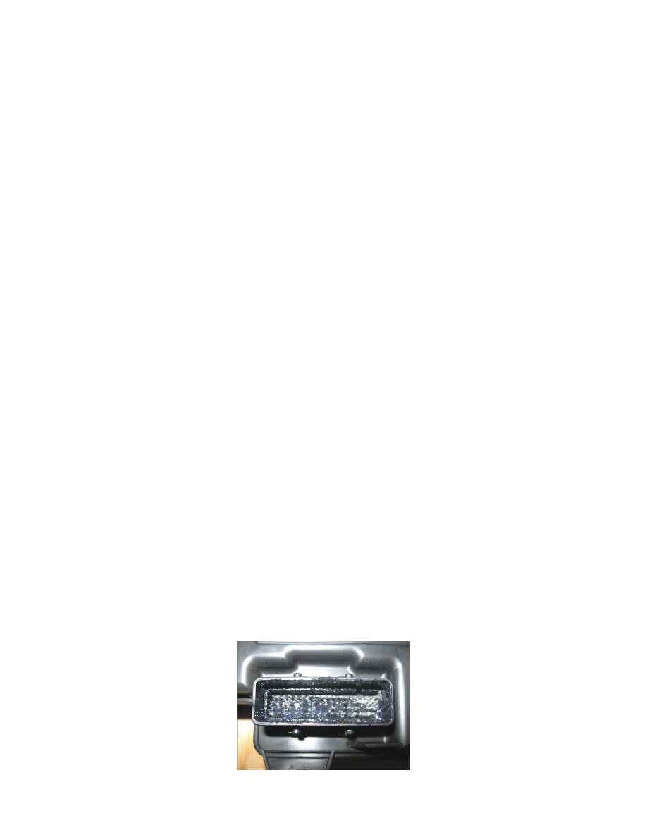
Fretting corrosion looks like little dark smudges on the electrical terminals and appear where the actual electrical contact is being made. In less
severe cases it may be unable to be seen or identified without the use of a magnifying glass.
1. If any water intrusion is present in the connector, use pressure regulated compressed air to dry it out.
2. DO NOT apply an excessive amount of dielectric lubricant as shown, to the connectors as hydrolock may result when attempting to mate the
connectors.