
Tahoe 4WD V8-393 6.5L DSL Turbo VIN S (1995)
setting to detect intermittents, it is necessary to connect the meter to the circuit.
Following are examples of the various methods of connecting the meter to the circuit to be checked:
^
Backprobe both ends of the connector and either hold the leads in place while manipulating the connector or tape the leads to the harness for
continuous monitoring while performing other operations or test driving. (Do not backprobe "Weather Pack(R)" type connectors.)
^
Disconnect the harness at both ends of the suspect circuit where it connects either to a component or to other harnesses.
^
Use Connector Test Adapter Kit J 35616-A to connect the meter to the circuit.
^
If the system being diagnosed has a specified Pinout or breakout box, it may be used to simplify connecting the meter to the circuit or for checking
multiple circuits quickly.
Aftermarket Accessories
Always check for aftermarket accessories (non-OEM) as the first step in diagnosing electrical problems. If the vehicle is so equipped, disconnect the
system to verify that these add-on accessories are not the cause of the problems.
Some possible causes of vehicle problems related to aftermarket accessories include:
1. Power feeds connected to points other than the Battery.
2. Antenna location.
3. Transceiver wiring located too close to vehicle electronic modules or wiring.
4. Poor shielding or poor connectors on antenna feed line.
Probing (Frontprobe & Backprobe)
After probing, when reconnecting connectors or replacing terminals, always be sure to reinstall Connector Position Assurance (CPA) and Terminal
Position Assurance (TPA).
Frontprobe
When frontprobing of connectors is required, always use a mating terminal adapter from Connector Test Adapter Kit (J 35616-A). The use of
proper adapters will ensure that proper terminal contact integrity is maintained. (refer to Procedures in Checking Terminal Contact).
Backprobe
Only backprobe connector terminals when specifically called for in diagnostic procedures. Since backprobing can be a source of damage to
connector terminals, extra care must be taken to avoid deforming the terminal, either by forcing the test probe too far into the cavity or by using
too large a test probe.
After backprobing any connector, always check for terminal damage. If terminal damage is suspected, check for proper terminal contact, refer to
Checking Terminal Contact. See: General Troubleshooting Procedures/Checking Terminal Contacts
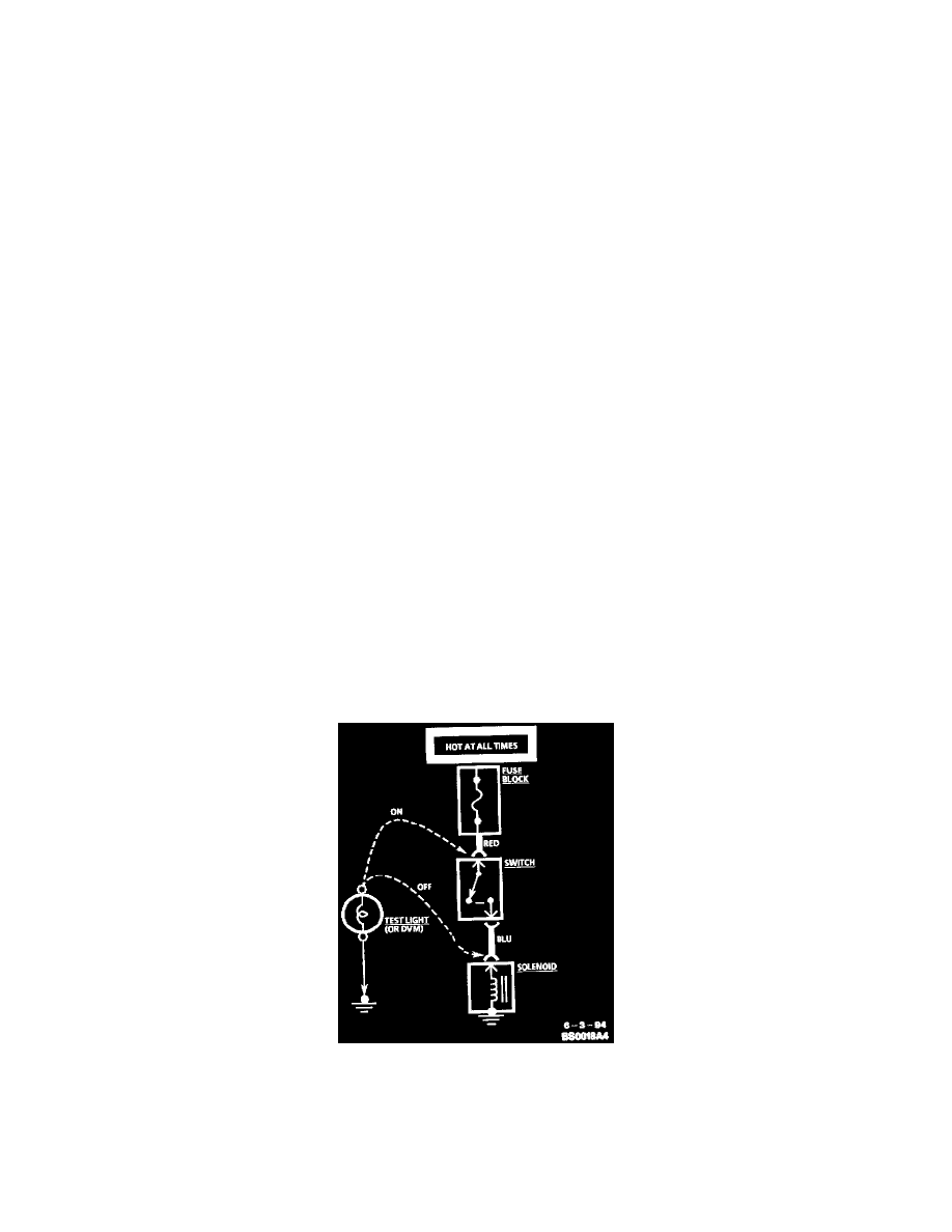
Testing For Voltage
Voltage Check
1. Connect one lead of a test light to a known good ground. When using a Digital Voltmeter (DVM), be sure the voltmeter's negative lead is
connected to ground.
2. Connect the other lead of the test light or voltmeter to a selected test point (connector or terminal).
3. If the test light illuminates, there is voltage present. When using a DVM, note the voltage reading.