
Tahoe 4WD V8-393 6.5L DSL Turbo VIN S (1995)
Differential Carrier: Adjustments
Timken/Rockwell - 12 Inch Ring Gear
Final Assembly & Adjustment
DRIVE PINION INSTALLATION
1.
Using micrometer or vernier gauge, measure and record thickness of original shim pack.
2.
Check P.C. number on original pinion. If number is positive, subtract it from original shim pack thickness. If number is negative, add it to original
shim pack thickness. Record resulting value.
3.
Check P.C. number on new pinion. If number is positive, add it to value obtained in step 2. If number is negative, subtract it from value obtained
in step 2.
4.
Figure obtained in step 3 indicates thickness of new shim pack to be used.
5.
Position correct shim pack between pinion cage and carrier.
Use a minimum of 3 shims per pack. If pack is made up from various thicknesses
of shims, place thinnest shims on either side of pack.
6.
Install pinion and cage assembly with shims into carrier and tap into position with soft mallet.
7.
Install pinion cage cap screws, torquing to 35 ft. lbs.
DIFFERENTIAL CASE INSTALLATION
1.
Temporarily install bearing cups, threaded adjusting rings if used, and bearing caps, torquing cap screws to 115-140 ft. lbs.
2.
If bearing cups are not of a hand push fit in bores, bores must be reworked with a scraper or emery cloth until a hand push fit is obtained. Use a
blued bearing cup as a gauge and check the fits as work progresses. When cups fit properly, remove bearing caps.
3.
After checking related parts, coat differential bearing cones and caps with rear axle lubricant.
4.
Place cups over assembled bearing cones and position differential assembly in carrier.
5.
Insert bearing adjusting nuts and turn hand-tight against bearing cups.
6.
Install bearing caps in correct location as marked and tap lightly in position.
If bearing caps cannot be properly seated bearing adjusters may
be cross-threaded. Remove bearing caps and reposition adjusting nuts as needed. Do not force bearing caps into position as carrier, caps
and adjusting nuts will be damaged.
7.
Install bearing cap bolts or nuts and washers, if used, then torque fasteners to 115-140 ft. lbs.
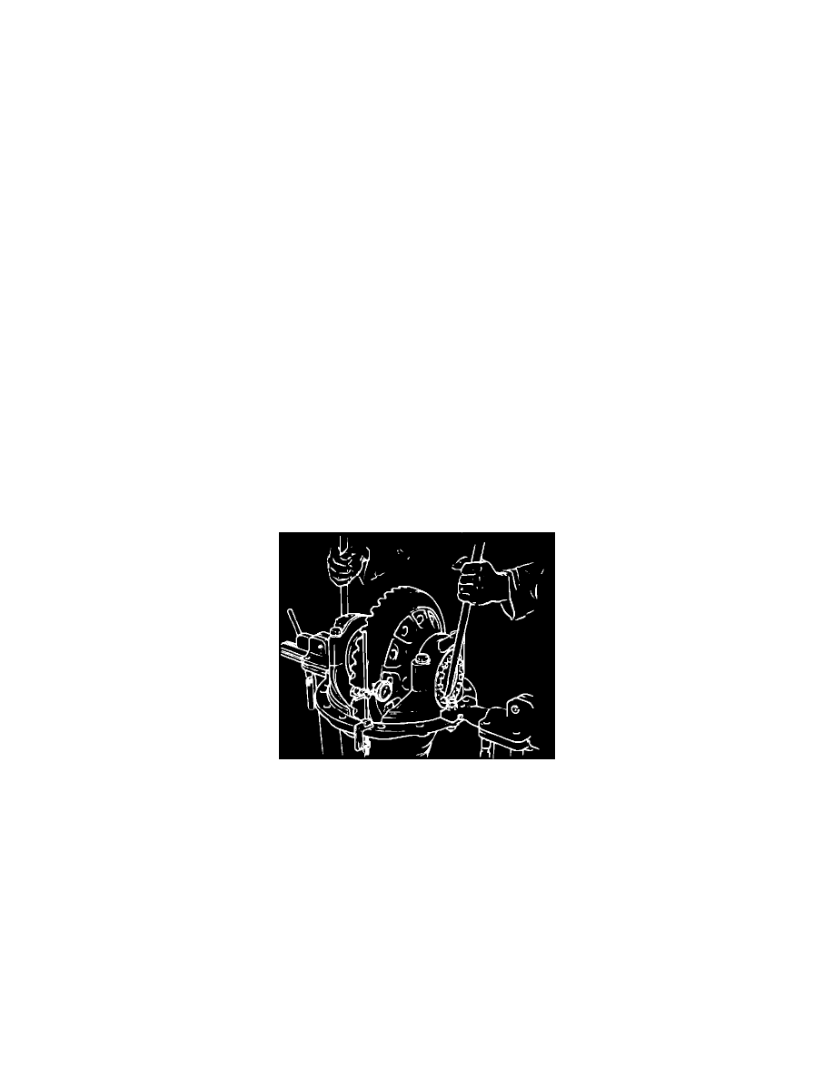
Fig. 8 Side Bearing Preload Adjustment