
Tahoe 4WD V8-393 6.5L DSL Turbo VIN S (1995)
GEAR TOOTH CONTACT INSPECTION
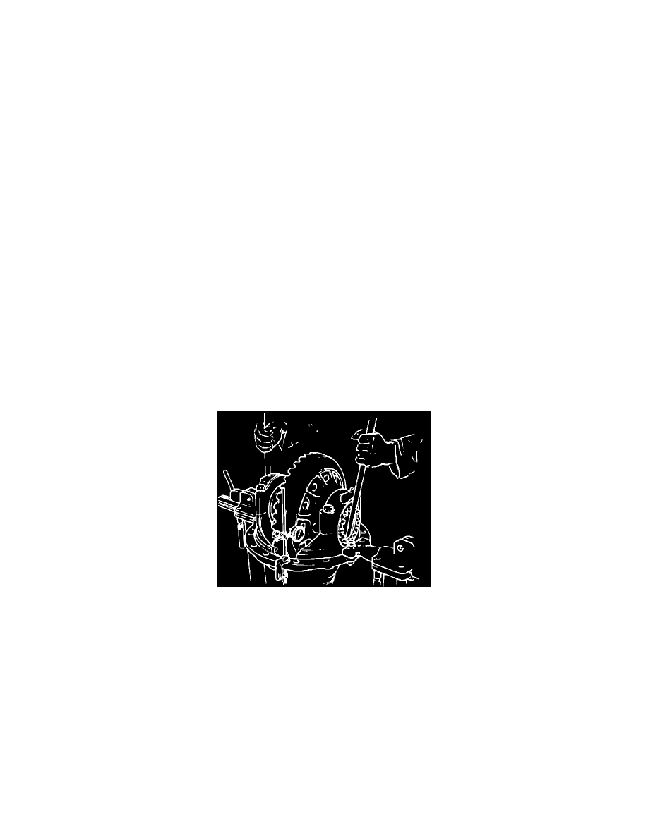
1.
Ensure that ring gear is clean and free from oil, then coat coast and drive face of each ring gear tooth with suitable marking compound.
2.
Brake ring gear to ``load'' gears, then turn pinion in order to rotate ring gear one full revolution in each direction.
Satisfactory contact pattern
cannot be obtained unless gears are ``loaded.'' Excessive rotation of gears is not recommended.
3.
Inspect tooth contact pattern referring to
Fig. 9, and correct assembly adjustments, as needed to obtain correct pattern.
4.
Clean marking compound from gears.
THRUST SCREW INSTALLATION & ADJUSTMENT
1.
Remove carrier from stand and position with back face of hypoid or spiral bevel gear upward.
2.
Remove thrust screw and locknut.
3.
Install thrust screw and locknut and tighten thrust screw enough to locate thrust block firmly against back face of hypoid gear.
4.
Loosen thrust screw 1/4 turn and lock securely with nut.
5.
Check to ensure minimum clearance of .10 inch during full rotation of bevel gear.
DIFFERENTIAL CARRIER, INSTALLATION
1.
Ensure that housing is clean and free from dirt and foreign material.
2.
Inspect housing for damage and distortion, and repair or replace as needed. Remove burrs from machined surfaces using suitable stone or file.
3.
Install new gasket over housing studs.
If RTV sealer is used, ensure that both mating surfaces are clean and free from oil, then apply a
continuous bead of sealer, 1/8 inch wide, completely around one mating surface, circling all bolt holes or studs.
4.
Raise carrier assembly with suitable jack, roll assembly onto studs, then install 4 evenly spaced flat washers and nuts to hold assembly.
5.
Install nuts and lock washers on any studs shrouded by housing webs, then evenly tighten 4 evenly spaced nuts to draw carrier into housing.
Do
not drive carrier into housing by tapping flange as flange will be distorted.
6.
Install lock washers under all retaining nuts, then evenly tighten all nuts.
7.
Install axle shafts and connect driveshaft to companion flange.
8.
Fill housing with specified lubricant.
Side Bearing Preload & Backlash
Fig. 8 Side Bearing Preload Adjustment