
Tahoe 4WD V8-393 6.5L DSL Turbo VIN S (1995)
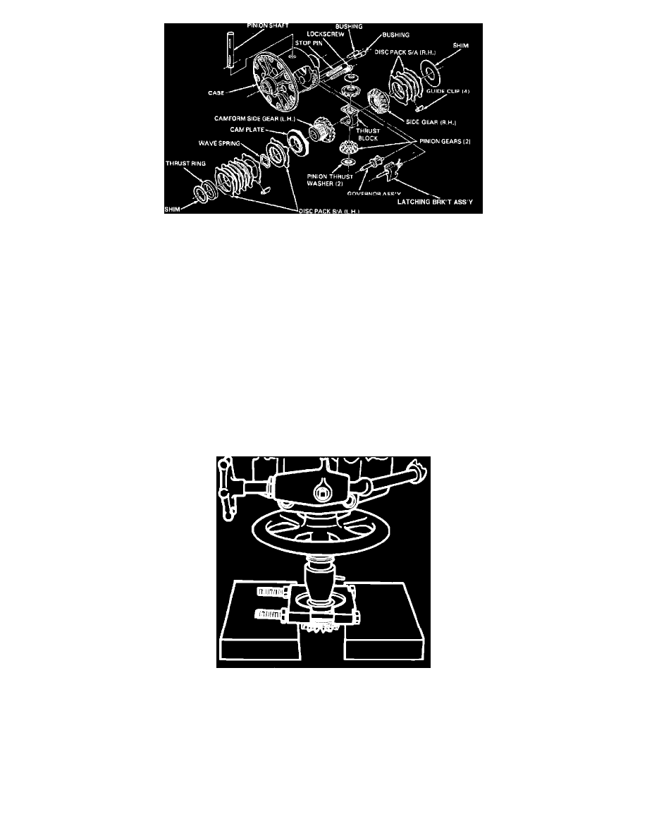
Fig. 5 Eaton locking differential exploded view
1.
Note position of governor and latching bracket,
Fig. 3, then remove side bearings and ring gear as outlined for standard differential.
2.
Remove governor and latching bracket bushings using J-26252 or equivalent,
Fig. 4, then the governor and latching bracket. Position latching
bracket spring aside when removing governor bushing to prevent damage.
3.
Drive stop pin from case using suitable drift,
Fig. 5.
4.
Remove differential pinion shaft lock bolt and the pinion shaft.
5.
Roll out differential pinions and remove pinions and thrust washers, keeping components in order for assembly.
6.
Remove right side gear, disc pack and shim, and guide clips.
7.
Remove left cam gear, disc pack assembly, shim and guide clips.
8.
Clean and inspect all components, keeping components in order for assembly, and replace components that are damaged, distorted or excessively
worn.
Due to critical tolerances required for proper operation, the differential case cannot be serviced separately. If case is defective, the
entire differential assembly must be replaced. In addition, internal clearances are such that shims, thrust block or gears should not be
replaced unnecessarily, even if slight wear patterns are evident. If shims, thrust block, cam gear thrust ring or side gears must be
replaced, measurement and replacement procedures must be followed as outlined in order to maintain critical assembly clearances.
Cam Gear Clutch Service
1.
Measure and record overall length of cam gear assembly from front face of gear to back side of thrust ring, including shim.
Fig. 6 Cam Gear Thrust Ring Removal. Eaton Locking Differential
2.
With gear hub facing up, compress disc pack and insert jaws of suitable split ring bearing puller between thrust ring and top eared disc with bevel
side of puller facing thrust ring,
Fig. 6.
3.
Support bearing remover in press and press cam gear from thrust ring using 1 3/4 inch diameter spacer. Keep all component in order as cam gear is
removed.
4.
Remove disc pack and cam plate from gear, clean and inspect components, and replace any that are damaged or excessively worn.
Do not replace
thrust ring and/or cam gear unless necessary. If ring or gear is excessively worn or scored, inspect bore in case. If case bore is scored,
entire assembly must be replaced. If cam gear or thrust ring are replaced, shim thickness must be selected to provide original assembly
dimension and proper differential pinion backlash.
5.
Position cam gear on flat surface with hub end up and install cam plate with cam form down to mate with form on gear.