
Tahoe 4WD V8-393 6.5L DSL Turbo VIN S (1995)
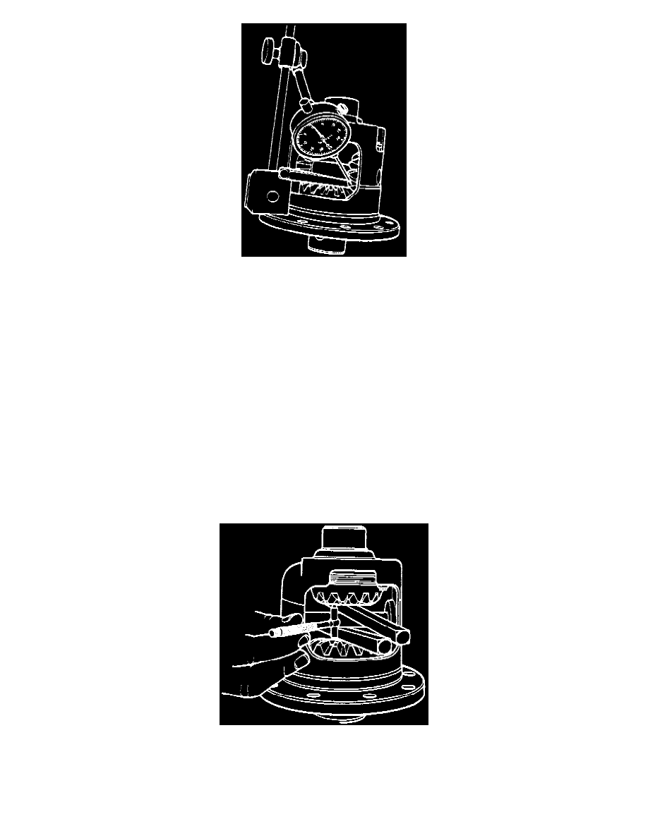
Fig. 9 Differential Pinion Backlash Inspection.
5. Mount suitable dial indicator on case with pointer bearing against indexed differential pinion tooth,
Fig. 9.
6. Ensure pinion is firmly pulled back in seat, then rock pinion back and forth, read backlash clearance from dial indicator and note reading.
7. Index tooth of opposite differential pinion as outlined in step 3, then repeat steps 5 and 6.
8. Replace cam gear assembly shim as needed to obtain differential pinion backlash of 0.010-0.018 inch.
If cam gear is replaced, perform Thrust
Block Selection procedure during case assembly to ensure proper case assembly clearances. Refer to Thrust Block Selection. See:
Corporate and Eaton/7 1/2 - 8 5/8 Inch Ring Gear/Overhaul/Eaton/Locking/Thrust Block Selection
Side Gear Shim Selection
When side gear is replaced, or if side gear shim is damaged and proper thickness must be determined, select proper side gear shim thickness by
measuring backlash between side gear and differential pinions. Follow procedure outlined for "Cam Gear Shim Selection, using fully assembled
side gear properly installed in case and select a shim that will provide 0.002-0.010 inch backlash between side gear and differential pinions.
Thrust Block Selection
If cam gear and/or side gear have been replaced, or if it is necessary to replace thrust block and original dimension cannot be determined, use the
following procedure during differential case assembling to determine proper thrust block dimension.
1. Install cam gear and side gear assemblies in respective positions in case, insert differential pinion shaft through case bores and secure with lock
screw.
2. Wedge large tapered screwdrivers or equivalent tools between cam gear and pinion shaft and side gear and pinion shaft to seat gears in case.
Fig. 10 Side Gear Spread Inspection.
3. Using suitable gauge, measure distance between face of cam gear and face of side gear,
Fig. 10, and record reading. Ensure gauge ends rest on
gear faces, not gear teeth when measuring side gear spread.
4. Measure thickness of original thrust block at outer corner and record dimension.
5. Select thrust block with thickness zero to 0.006 inch less than side gear spread measured in step 3.
If original thrust block is serviceable, but