
Tahoe 4WD V8-393 6.5L DSL Turbo VIN S (1995)
block clearance, as long as specified .002-.010 inch backlash between side gear and differential pinions is maintained.
Differential Case Assembly
1.
Install 4 guide clips on cam gear clutch ears, using grease for retention.
2.
Install cam gear assembly along with selected shim into case noting the following:
a. If cam gear was replaced, select shim. Refer to
Shim Selection. See: Corporate and Eaton/9 1/2 Inch Ring Gear/Overhaul/Eaton
Locking/Shim Selection
b. If cam gear thrust ring was replaced, measure length of entire cam gear assembly, including shim.
c. If measurement varies more than .003 inch from length measured during disassembly, select and install shim that will return assembly to
original length.
Incorrect shimming will result in differential malfunction and may cause premature failure.
3.
Mount axle shaft in vise with spline protruding enough to engage cam gear, then mount case assembly over shaft engaging shaft in gear.
4.
Install 4 small guide clips on ears of side gear clutch pack, using grease to retain clips.
5.
Install thrust washers on differential pinions, using grease to adhere washers.
6.
Install side gear assembly along with selected shim in case, insert one pinion through small opening in case while simultaneously installing
remaining pinion and thrust block through large opening, then rotate case assembly on axle shaft to position pinions in line with shaft opening and
thrust block with open side toward small opening in case.
Thrust block clearance is critical to proper differential operation. If either side
gear, shims or cam gear thrust ring have been replaced, check side gear spread as outlined in Thrust Block Selection, and select thrust
block which will provide zero to .006 inch clearance. Refer to Thrust Block Selection. See: Corporate and Eaton/9 1/2 Inch Ring
Gear/Overhaul/Eaton Locking/Thrust Block Selection
7.
Ensure that pinions and thrust washers are properly positioned, then install pinion shaft and secure with lock screw. Do not torque lock screw until
axle shafts have been installed.
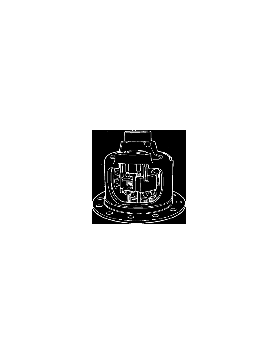
Fig. 3 Governor & latching bracket installation. Eaton locking differential
8.
Insert governor assembly and latching bracket into case, placing straight end of latching bracket spring over and to outside of engagement shaft to
preload bracket against governor,
Fig. 3.
9.
Press governor and latching bracket bushings into case as follows:
a. Press governor bushing in to a depth that will provide .004-.020 inch endplay.
b. Press bracket bushing in to a depth that will just eliminate endplay.
c. Press stop pin in until flush with top of case.
10.
Install ring gear and side bearings. Refer to
Corporate - Standard. See: Corporate and Eaton/9 1/2 Inch Ring Gear/Overhaul/Corporate -
Standard
Disassembly