
Tahoe 4WD V8-393 6.5L DSL Turbo VIN S (1995)
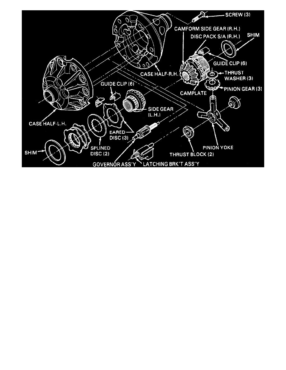
Fig. 2 Eaton locking differential exploded view
1.
Remove side bearings and ring gear as outlined for standard differential.
2.
Remove 3 case retaining screws from ring gear mounting flange, then set unit on right case half,
Fig. 2.
3.
Carefully pry case apart at yoke opening, hold side gear assembly in case, then remove left case half.
4.
Note installation position, then remove governor and latching bracket.
5.
Remove thrust blocks, yoke and differential pinions, noting installation position for assembly.
6.
Remove cam gear and disc assembly, shim and guide clips from right case half.
7.
Remove side gear, disc pack and shim, and guide clips from left case half.
8.
Clean and inspect all components, keeping components in order for proper assembly. Replace any components that are damaged, distorted or
excessively worn.
Due to critical tolerances required for proper operation, the differential case cannot be serviced separately. If case is
defective, the entire differential assembly must be replaced. In addition, internal clearances are such that shims, thrust blocks, side gears
or cam gear thrust ring should not be replaced unnecessarily, even if slight wear patterns are evident. If shims, thrust blocks, side gears
or thrust ring must be replaced, measurement and replacement procedures must be performed as outlined in order to maintain critical
assembly clearances.
Cam Gear Clutch Service
1.
Measure and record overall length of cam gear assembly from front face of gear to back face of thrust ring, including shim.
2.
Compress disc pack and insert jaws of bearing separator J-22912 or equivalent between thrust ring and top clutch disc with chamfer of separator
facing thrust ring.