
Tahoe 4WD V8-393 6.5L DSL Turbo VIN S (1995)
4.
Slightly loosen bolt clamping cam gear into case and index one pinion gear tooth so that it points downward, perpendicular to parting line of case,
then retighten cam gear clamping bolt.
5.
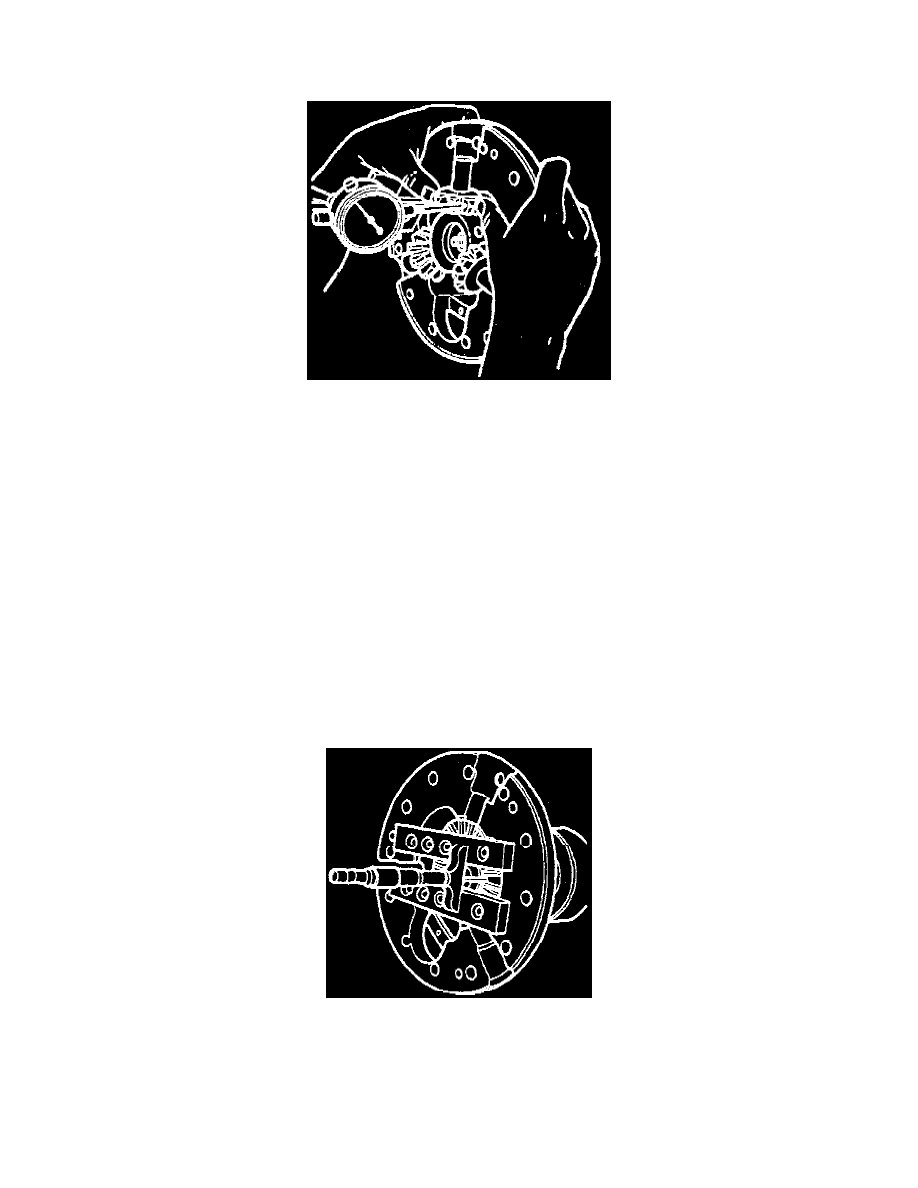
Mount suitable dial indicator on case with plunger contact bearing against tooth indexed in step 4.
6.
Firmly hold pinion into seat, rock pinion back and forth against cam gear and record backlash reading from dial indicator,
Fig. 6.
7.
Repeat steps 4 through 6 with each remaining pinion, then select cam gear shim that will provide .010-.018 inch backlash between all pinions and
cam gear.
When cam gear and/or shim is replaced, thrust blocks must be measured and selected to maintain proper clearance during
assembly.
Side Gear Shim Selection
If side gear is replaced, or if original shim thickness cannot be measured, select proper side gear shim thickness by measuring backlash between side
gear and differential pinions. Follow procedure for Cam Gear Shim Selection, using fully assembled side gear installed in left case half. Refer to
Cam
Gear Shim Selection. See: Corporate and Eaton/10 1/2 Inch Ring Gear/Overhaul/Eaton Locking/Cam Gear Shim Selection
Select a shim that will provide .002-.010 inch backlash between side gear and differential pinions. If side gear and/or shim is replaced, refer to ``Thrust
Block Selection'' during case assembly in order to install thrust block that will maintain proper assembly clearances.
Thrust Block Selection
If cam gear, side gear and/or shims are replaced, or if thrust blocks must be replaced and original dimension cannot be determined, use following
procedure during case assembly to determine proper thrust block size.
1.
Secure fully assembled cam gear and side gear assemblies into respective case halves as outlined in shim selection procedure. Refer to
Cam Gear
Shim Selection. See: Corporate and Eaton/10 1/2 Inch Ring Gear/Overhaul/Eaton Locking/Cam Gear Shim Selection
2.
Using suitable gauge block and depth gauge, measure distance from each gear face to case mounting surface,
Fig. 7, and record dimension.
3.
Add together cam gear and side gear depth measurements to obtain side gear spread.
When adding dimensions measured in step 2, be sure to
subtract thickness of gauge block from each measurement.