
Tahoe 4WD V8-393 6.5L DSL Turbo VIN S (1995)
17. Examine gear tooth contact pattern, referring to
Fig. 6, and correct assembly adjustments as needed.
18. Install housing covers, using a new gasket, and
torque attaching bolts to 35 ft. lbs.
19. Install rear universal joint, on rear drive axles, then the axle shafts.
20. Fill axle with specified lubricant.
10 1/2 and 11 Inch Ring Gear
1. Install differential case with side bearings and cups in position, into carrier.
2. Place the smallest of original shims between bearing cup and carrier on ring gear side of case. This shim will act as a gauging shim.
3. Install bearing caps in proper position and tighten just enough to retain in place.
4. Install a dial indicator on ring gear side of carrier with indicator button contacting back of ring gear.
5. Position two screwdrivers between bearing cup and housing on side opposite ring gear.
6. Apply force to screwdrivers to move differential case as far as possible toward the indicator.
7. Set dial indicator to 0 with force still applied to screwdrivers.
8. Reposition screwdrivers on ring gear side of case, then force ring gear into mesh with drive pinion and note dial indicator reading. Repeat
sequence several times until same reading is obtained. Add this reading to "gauging" shim thickness to determine shim required on ring gear side
of case.
9. Remove "gauging shim and install correct thickness shim between bearing cup and carrier on ring gear side of case.
10. To determine correct dimension for remaining shim, subtract size of shim already installed from reading obtained in step 10 of Overhaul
procedure. Refer to
Overhaul. See: Dana/Spicer Full Floating Axle/Overhaul
On 10 1/2 inch axles, add an 0.006 inch to this figure to compensate for preload and backlash, on 11 inch, add 0.010 inch.
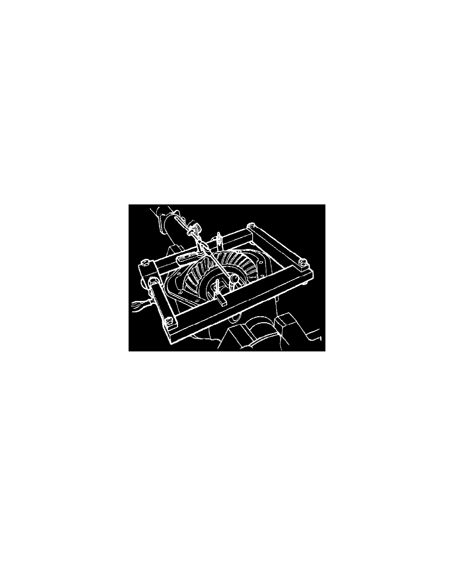
Fig. 3 Differential Carrier Spreading.
11. Spread differential carrier,
Fig. 3, then install shim between bearing cup and carrier.
12. Remove spreader tool and dial indicator, then install bearing caps and
torque cap bolts to 85 ft. lbs.
13. Install dial indicator and check ring gear backlash at four equidistant points on the ring gear. Backlash must measure 0.004-0.009 inch and must
not vary more than 0.002 inch between checking points.
If backlash is not within specifications, adjust differential bearing shim pack as
necessary. If backlash is less than specifications, decrease shim on ring gear side and increase shim on opposite side an equal amount. If
backlash exceeds specifications, increase shim on ring gear side and decrease shim on opposite side an equal amount.
14. Ensure ring gear teeth are clean and free from oil, then coat drive and coast face of each tooth with suitable marking compound.
15. Apply braking force to ring gear, then turn pinion to rotate ring gear one complete revolution in each direction.
Accurate contact pattern cannot
be obtained unless gears are "loaded when rotated.