
Tahoe 4WD V8-393 6.5L DSL Turbo VIN S (1995)
2. Oil seal using J 36366.
^
Position the oil seal in the bore, then place J 36366 over the oil seal. Strike J 36366 with a hammer until the seal flange is seated on the axle
housing surface. Drive the seal in straight, not at an angle, as this will damage the aluminum housing.
NOTICE: Do not hammer the pinion flange onto the pinion shaft or the pinion flange may be damaged.
3. Flange onto the pinion using J 8614-01.
^
Place the washer and a new nut on the pinion threads and tighten the nut to the original scribed position using the scribe marks and exposed
threads as a reference.
Measure
^
The rotating torque of the pinion and compare this with the rotating torque recorded earlier.
Tighten
^
The pinion nut by small increments until the torque required to rotate the pinion is 0.35 Nm (3 inch lbs.) greater than the original torque.
4. Propeller shaft.
5. Lower the vehicle.
Semi-Floating Axle 8-1/2, 8-5/8 and 9-1/2 Inch Ring Gear
^
Tools Required:
-
J 8614-01 Companion Flange Holder:
-
J 8614-02 Companion Flange Remover
-
J 24388 Pinion Oil Seal Installer (American Axle 9 1/2 inch ring gear axle)
-
J 22836 Pinion Oil Seal Installer (American Axle 8 1/2 and 8 5/8 inch ring gear axles)
-
J 22804 Pinion Oil Seal Spacer
^
The pinion oil seal and the companion flange may be replaced with the carrier assembly installed in the vehicle.
REMOVE OR DISCONNECT
^
Raise the vehicle on a hoist and support with safety stands.
1. Rear wheels and drums.
Important:
^
It is essential that the positions of all driveline components relative to the propeller shaft and axles be observed and accurately reference
marked prior to disassembly. These components include the propeller shafts, drive axles, pinion flanges, output shafts, etc. All components
must be reassembled in the exact relationship to each other as they were when removed. Specifications and torque values, as well as any
measurements made prior to disassembly, must be followed.
^
Accurately mark the installed position of the rear propeller shaft.
2. Propeller shaft.
A. Use a piece of tape to hold the bearing caps.
B. Secure the propeller shaft up and out of the way so as not to put unnecessary stress on the universal joints.
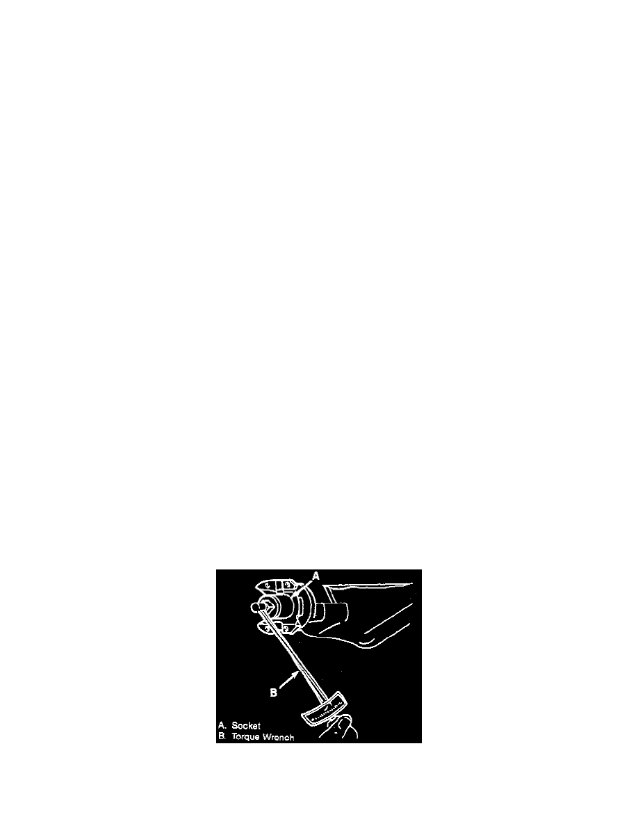
C. Measure, using an inch-pound torque wrench, the amount of torque required to turn the pinion. Record this measurement for reassembly. This
will give combined pinion bearing, seal, carrier bearing, axle bearing and seal preload.