
Tahoe 4WD V8-6.2L (2009)
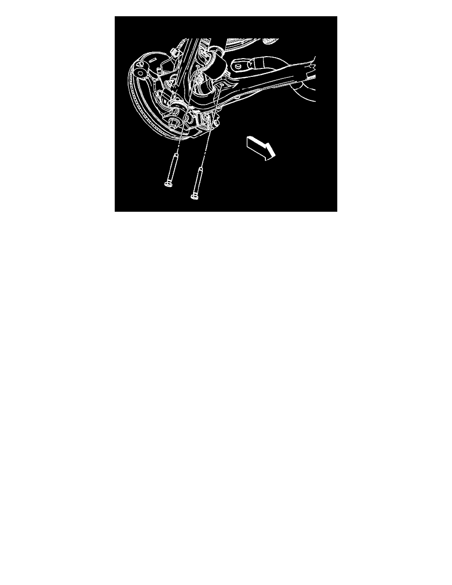
7. Install the lower shock absorber module mount bolts and tighten to 50 Nm(37 lb ft).
8. Remove the support for the steering knuckle and upper control arm.
9. Install the wheel drive shaft, if equipped. Refer to Wheel Drive Shaft Replacement (2500) (See: Transmission and Drivetrain/Drive Axles,
Bearings and Joints/Axle Shaft Assembly/Service and Repair/Wheel Drive Shaft Replacement - 2500 Series)Wheel Drive Shaft Replacement
(1500) (See: Transmission and Drivetrain/Drive Axles, Bearings and Joints/Axle Shaft Assembly/Service and Repair/Wheel Drive Shaft
Replacement - 1500 Series).
10. Install the stabilizer shaft link to the lower control arm. Refer to Stabilizer Shaft Link Replacement (1500) (See: Stabilizer Bar/Stabilizer
Link/Service and Repair/Front Suspension/Stabilizer Shaft Link Replacement (1500))Stabilizer Shaft Link Replacement (2500) (See: Stabilizer
Bar/Stabilizer Link/Service and Repair/Front Suspension/Stabilizer Shaft Link Replacement (2500)).
11. Install the tire and wheel. Refer to Tire and Wheel Removal and Installation (See: Wheels and Tires/Service and Repair).
12. Remove the support and lower the vehicle.
13. Align the front end. Refer to Wheel Alignment Measurement (See: Alignment/Service and Repair/Wheel Alignment Measurement).
Lower Control Arm Replacement (2500)
Lower Control Arm Replacement (2500)
Special Tools
*
J 43631 - Ball Joint Separator
*
J 45851 - Ball Joint Separator Protector Adapters
Removal Procedure
Note: For vehicles equipped with the aluminum control arm, the ball joint is NOT serviced separately. If the ball joint is found to have excessive wear
and is damaged, replace the lower control arm as an assembly.
1. Raise and support the vehicle. Refer to Lifting and Jacking the Vehicle (See: Wheels and Tires/Vehicle Lifting/Service and Repair).
2. Remove the tire and wheel. Refer to Tire and Wheel Removal and Installation (See: Wheels and Tires/Service and Repair).
3. Remove the stabilizer shaft link from the lower control arm. Refer to Stabilizer Shaft Replacement (1500) (See: Stabilizer Bar/Service and
Repair/Front Suspension/Stabilizer Shaft Replacement (1500))Stabilizer Shaft Replacement (2500) (See: Stabilizer Bar/Service and Repair/Front
Suspension/Stabilizer Shaft Replacement (2500)).
4. Remove the torsion bars. Refer to Torsion Bar and Support Assembly Replacement (Bushing Style) (See: Torsion Bar/Service and
Repair/Torsion Bar and Support Assembly Replacement (Bushing Style))Torsion Bar and Support Assembly Replacement (Link Style) (See:
Torsion Bar/Service and Repair/Torsion Bar and Support Assembly Replacement (Link Style)).
5. Remove the shock absorber. Refer to Shock Absorber Replacement (2500 Series) (See: Suspension Strut / Shock Absorber/Service and
Repair/Front Suspension Shock Absorber/Shock Absorber Replacement (2500 Series)).
6. Remove the wheel drive shaft. Refer to Wheel Drive Shaft Replacement (2500) (See: Transmission and Drivetrain/Drive Axles, Bearings and
Joints/Axle Shaft Assembly/Service and Repair/Wheel Drive Shaft Replacement - 2500 Series)Wheel Drive Shaft Replacement (1500) (See:
Transmission and Drivetrain/Drive Axles, Bearings and Joints/Axle Shaft Assembly/Service and Repair/Wheel Drive Shaft Replacement - 1500
Series).