
Tracker 2WD L4-1.6L VIN 6 (2000)
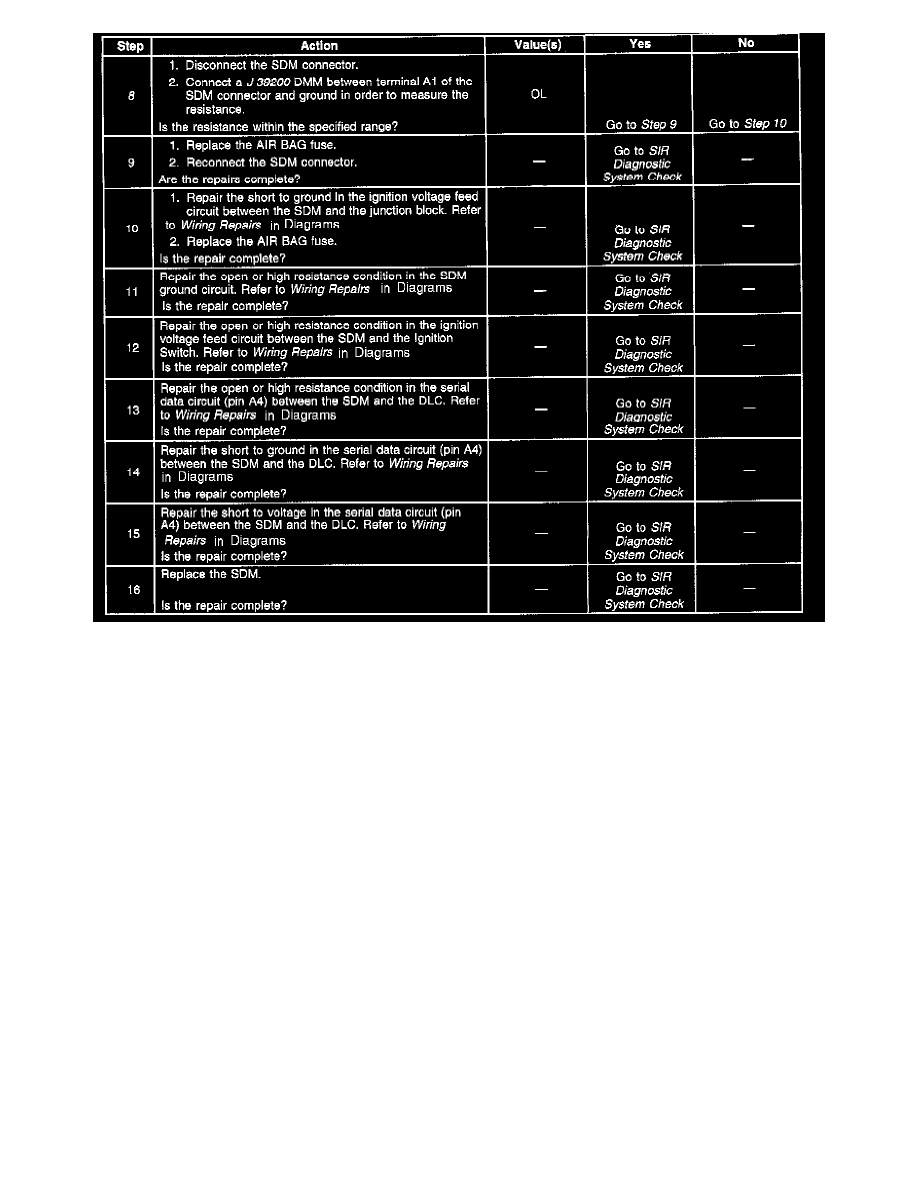
Scan Tool Does Not Communicate With SDM (Part 2 Of 2)
Refer to Restraint Systems Schematics in Restraint Systems and Data Link Connector Schematics
CIRCUIT DESCRIPTION
The data link connector (DLC) is the provision for communicating with the inflatable restraint sensing and diagnostic module (SDM). The DLC is
located under the instrument panel. The DLC supplies Battery voltage and ground to the scan tool. The scan tool communicates with the SDM on the
serial data line. The scan tool is connected to the DLC in order to perform the following functions:
^
Read the data list
^
Read diagnostic trouble codes (DTCs)
^
Clear DTCs
When measurements are requested in this table, use J 39200 Digital Multimeter with the correct terminal adapter from J 35616-A Connector Test
Adapter Kit. When a check for proper connection is requested, refer to General Electrical Diagnosis Procedures in Wiring Systems. When a wire,
connector or terminal repair is requested, use J 38125-B Terminal Repair Kit and refer to Wiring Repairs in Diagrams.
TEST DESCRIPTION
3. This test checks for an open or high resistance condition in the SDM ground circuit.
4. This test checks for an open or high resistance condition in the SDM voltage feed circuit.
5. This test checks for an open or high resistance condition in the serial data circuit.
6. This test checks for a short to ground condition in the serial data circuit.
7. This test checks for a short to voltage condition in the serial data circuit.
8. This test checks for a short to ground condition in the SDM voltage feed circuit.
Scan Tool Does Not Communicate With VCM/PCM