
Tracker 2WD L4-1.6L VIN 6 (2000)
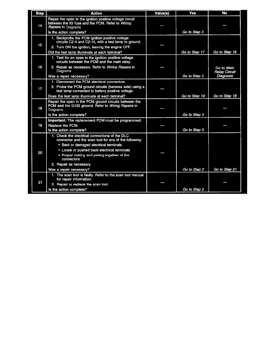
Diagnostic Chart (Part 2 Of 2)
Refer to Engine Controls Power And Ground Schematics and Engine Controls MIL and DLC Schematics.
CIRCUIT DESCRIPTION
The provision for communicating with the Powertrain Control Module (PCM) is the Data Link Connector (DLC). The DLC is located under the
instrument panel. The DLC is used to link a scan tool to the PCM serial data stream. Some common uses of the scan tool are listed below:
^
Identifying the stored Diagnostic Trouble Codes (DTCs)
^
Reading the serial data stream
^
Clearing the DTCs
^
Storing the Freeze Frame data
DIAGNOSTIC AIDS
Some scan tools may require an external power supply. Make sure that your scan tool is using the correct power feed.
Check that the correct application (model year, carline, VIN code) has been selected on the scan tool. If communications are still not established, try
the scan tool on another vehicle in order to ensure that the scan tool or the connecting cables are not the cause of the malfunction.
Any circuitry that is suspect to an intermittent complaint should be thoroughly inspected for any of the following conditions:
^
Backed out terminals
^
Improper mating of terminals
^
Broken electrical connector locks
^
Improperly formed or damaged terminals
^
Faulty terminal to wire connections
^
Physical damage to the wiring harness
^
Broken conductor inside the wire insulation
^
Corrosion of electrical connections, splices, or terminals