
Tracker 2WD L4-2.0L VIN C (1999)
during this driving event, may not consider it a trip. No trip will occur for that particular diagnostic until the vehicle is driven in such a way as to meet all
the enable criteria.
Passive and Active Diagnostic Tests
A passive test is a diagnostic test which simply monitors a vehicle system or a vehicle component. An active test actually takes some sort of action when
the performing diagnostic functions. An active test is often in response to a failed passive test. For example, the Exhaust Gas Recirculation (EGR)
diagnostic active test may force the EGR valve open during a closed throttle deceleration maneuver. Or the EGR diagnostic active test may force the
EGR valve closed during a period of steady speed driving. Either action should result in a change in the manifold pressure.
Warm-Up Cycle
A warm-up cycle means that the engine temperature must reach a minimum of 70°C (160°F) and rise at least 22°C (40°F) over the course of a trip.
Freeze Frame and Failure Records
Storing Freeze Frame And Failure Record Data
Freeze Frame is an element of the Diagnostic Management System that stores various vehicle information in the PCM memory at the moment an
emissions-related fault occurs that commands the Malfunction Indicator Lamp (MIL) ON. Freeze Frame data is useful in identifying the cause of an
emission-related fault. Freeze Frame data is accessed by the scan tool and can be saved with the Capture Data feature. Refer to Storing And Erasing the
Freeze Frame data in PCM Diagnosis for more detailed information.
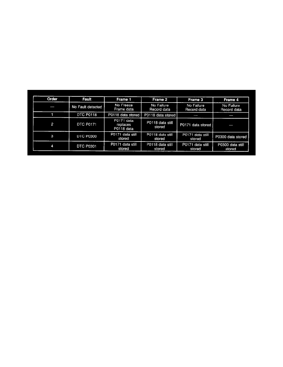
The PCM can store one Freeze Frame and save the recorded data of three additional Freeze Frames as Failure Records. Therefore the PCM can store up
to 4 frames of Freeze Frame and Failure Record data. The 1st frame stores data of the fault that was detected first. The data from the 1st detected fault is
also stored in the 2nd frame as a Failure Record. The Failure Record data stored in the 2nd frame is permanent, and will not change when a new fault is
detected. The 1st frame of Freeze Frame data will remain unchanged unless a fault of a higher priority occurs. A misfire fault (DTC P0300-P0304) or a
fuel trim fault (DTC P0171 and P0172) will replace the data in the 1st frame of Freeze Frame data because these DTCs have a higher priority under
OBD II rules. The 2nd through 4th frames of Failure Records will store fault data in the order that the faults were detected regardless of the priority of
the fault. Utilizing the 4 frames of Freeze Frame and Failure Record data can provide information on the order in which the faults were first detected.
The following table indicates how Freeze Frame and Failure Record data is stored when two or more faults are detected.
Diagnostic Information
The diagnostic tables and the functional checks are designed to locate a faulty circuit or component through a process of logical decisions. The
diagnostic tables are prepared with the requirement that the vehicle functioned correctly at the time of assembly and that there are not multiple faults
present.
There is a continuous self-diagnosis on certain control functions. This diagnostic capability is complemented by the diagnostic procedures contained in
this service information. The language of communicating the source of the malfunction is a system of Diagnostic Trouble Codes (DTCs). When a
malfunction is detected by the PCM, a DTC is set and the MIL is illuminated.
Malfunction Indicator Lamp (MIL)
The Malfunction Indicator Lamp (MIL) looks the same as the MIL you may already be familiar with, such as Service Engine Soon or Check Engine.
OBD II regulations require that the MIL illuminate according to a strict set of guidelines. Under OBD II the MIL is illuminated when the PCM detects a
malfunction that will impact the vehicle emissions.
The MIL is controlled by the PCM. The MIL will be illuminated if an emissions-related diagnostic test indicates a malfunction has occurred. The MIL
will stay illuminated until the system or the component passes the same test for three consecutive trips.
A vehicle that is experiencing a misfire malfunction that may cause damage to the Three-way Catalytic Converter (TWC) will flash the MIL once per
second. The MIL will continue to flash once per second until the vehicle is outside of the speed and the load conditions that may cause damage to the
TWC catalyst. The MIL will stop flashing and remain ON steady once the vehicle is outside of the speed and the load conditions that may cause damage