
Tracker 4WD V6-2.5L VIN 4 (2001)
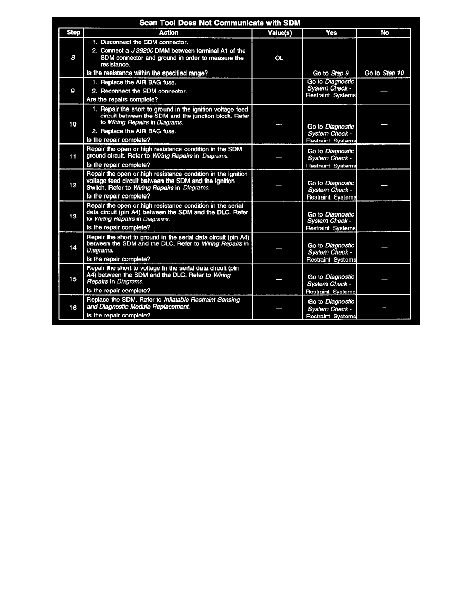
Steps 8-16
3. This test checks for an open or high resistance condition in the SDM ground circuit.
4. This test checks for an open or high resistance condition in the SDM voltage feed circuit.
5. This test checks for an open or high resistance condition in the serial data circuit.
6. This test checks for a short to ground condition in the serial data circuit.
7. This test checks for a short to voltage condition in the serial data circuit.
8. This test checks for a short to ground condition in the SDM voltage feed circuit.
Scan Tool Does Not Communicate With VCM/PCM
CIRCUIT DESCRIPTION
The provision for communicating with the Powertrain Control Module (PCM) is the Data Link Connector (DLC). The DLC is located under the
instrument panel. The DLC is used to link a scan tool to the PCM serial data stream. Some common uses of the scan tool are listed below:
^
Identifying the stored Diagnostic Trouble Codes (DTCs)
^
Reading the serial data stream
^
Clearing the DTCs
^
Storing the Freeze Frame data
DIAGNOSTIC AIDS
Some scan tools may require an external power supply. Make sure that your scan tool is using the correct power feed.
Check that the correct application (model year, carline, VIN code) has been selected on the scan tool. If communications are still not established, try
the scan tool on another vehicle in order to ensure that the scan tool or the connecting cables are not the cause of the malfunction.
An intermittent malfunction may be caused by a fault in the serial data circuit. Inspect the wiring harness and components for an intermittent condition.
Refer to Intermittent Conditions in Computers and Control Systems.
TEST DESCRIPTION