
Tracker 4WD V6-2.5L VIN 4 (2001)
Steps 9-17
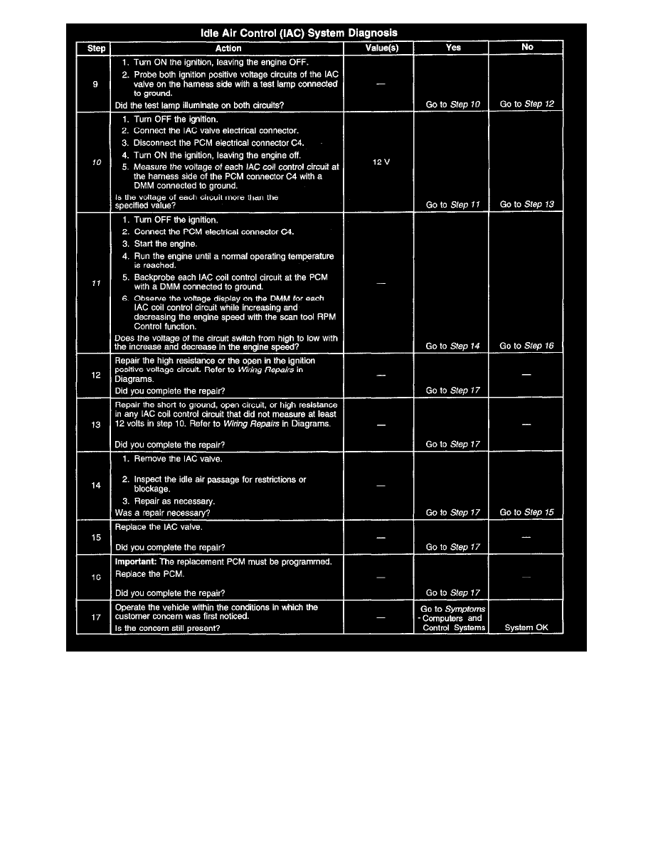
The numbers below refer to the step numbers in the diagnostic table.
1. A Diagnostic System Check-Computers and Control Systems prompts the technician to complete some basic checks and store the Freeze Frame
data on the scan tool if applicable. This creates an electronic copy of the data taken when the fault occurred. The information is then stored in the
scan tool for later reference.
4. This step tests whether the PCM can operate the IAC valve with the scan tool. The IAC valve can be commanded to increase and/or decrease
engine speed by using the scan tool RPM Control function. The RPM Control function of the scan tool is disabled when any DTCs are set, and
when the engine is less than the normal operating temperature of 80°C (176°F).
5. This step checks the operation of the electrical load idle-up circuits. If there is no increase in the IAC Duty Cycle percentage when the accessory is
turned on, the idle-up circuit may be inoperative or always on.
6. This step checks the operation of the A/C idle-up circuits. If there is no increase in the IAC Duty Cycle percentage when the A/C compressor is