
TrailBlazer 2WD L6-4.2L VIN S (2003)
5.
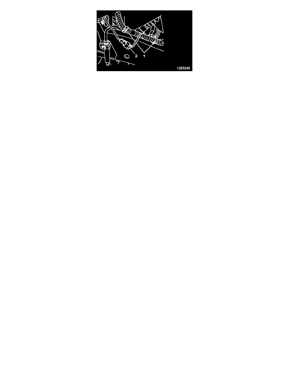
Release the wiring harness from the retaining clips (2) on the frame and reposition the harness as necessary to allow for removal of the brake pipe.
6.
Disconnect the wheel speed sensor harness connector (1) located on the outboard side of the left frame rail near the front caliper brake hose fitting.
7.
From the left front wheelhouse, remove the brake pipe from the vehicle.
8.
Position the new brake pipe to the vehicle and install it in the retainers on the frame.
Notice
To avoid damaging the threads on the ABS modulator, flare nuts, or the front brake hose fitting, use only your fingers to start the threads. Do
not use tools to start threading the flare nut into the ABS modulator or the front brake hose fitting.
9.
Connect the brake pipe to the ABS modulator and tighten the flare nut. Tighten to 20 N.m (15 lb ft).
10.
Connect the brake pipe to the left front caliper brake hose fitting. Tighten lighten the flare nut to 20 N.m (15 lb ft).
11.
Position the wiring harness to the frame and secure in the retainers.
12.
Connect the wheel speed sensor harness connector.
Important
Do not drive the vehicle until the brake pedal feels firm. Do not reuse brake fluid that is used during bleeding.
13.
Lower the vehicle as necessary to allow for manual bleeding of the left front brake assembly.
Caution
Refer to Brake Fluid Caution in the Cautions and Notices in the appropriate Service Manual.
Notice
Refer to Brake Fluid Effects on Paint and Electrical Components Notice in Cautions and Notices in the appropriate Service Manual.
Notice
When adding fluid to the brake master cylinder reservoir, use only DOT-3 brake fluid from a clean, sealed brake fluid container. The use of
any type of fluid other than the recommended type of brake fluid may cause contamination, which could result in damage to the internal rubber
seals and/or rubber linings of hydraulic brake system components.
Important
Clean the outside of the reservoir on and around the reservoir cap prior to removing the cap and diaphragm in the next step.
14.
Fill the brake master cylinder reservoir with Delco Supreme 11(R), GM P/N 12377967, Canadian P/N 89021320, or equivalent DOT-3 brake fluid
from a clean sealed brake fluid container.
15.
Install the J 35589-A to the brake master cylinder reservoir.
16.
Check the brake fluid level in the J 29532, or equivalent. Add Delco Supreme 11(R) or equivalent DOT-3 brake fluid from a clean sealed brake
fluid container as necessary to bring the level to approximately the half-full point.
17.
Connect the J 29532, or equivalent, to the J 35589-A.
18.
Charge the J 29532, or equivalent, air tank to 175-205 kPa (25-30 psi).
19.
Open the J 29532, or equivalent, fluid tank valve to allow pressurized brake fluid to enter the brake system.