
TrailBlazer 2WD L6-4.2L VIN S (2003)
1. Remove the connector position assurance (CPA) device and/or the secondary lock.
2. Disconnect the connector from the component or separate the connectors for in-line connectors.
3. Remove the terminal position assurance (TPA) device.
4. Insert the proper pick or removal tool into the front of the connector body.
5. Grasp the wire at the back of the connector body and gently push the terminal (1) out the front of the connector body (3).
IMPORTANT: On connectors with more than one terminal the service loop may not be large enough to remove the terminal and crimp on a new
one. If the terminal wire does not have a large enough service loop for removal, cut the wire 5 cm (2 in) behind the connector before removal.
TERMINAL REPAIR
1. If the wire needed to be cut in order to remove the terminal, gently push a small length of the same size wire through the back of the connector
cavity until there is enough wire exposed in order to crimp on a new terminal. If the wire was not cut, cut the existing wire as close to the old
terminal as possible.
2. Strip 5 mm (3/16 in) of insulation from the wire.
3. Crimp a new terminal to the wire.
4. Solder the crimp with rosin core solder.
TERMINAL INSTALLATION
1. Align the terminal and pull the wire from the back of the connector in order to seat the terminal.
2. If necessary, cut the new wire to proper length and splice with existing circuit. Refer to Splicing Copper Wire Using Splice Sleeves.
3. If the connector is outside of the passenger compartment, apply dielectric grease to the connector.
4. Install the TPA, CPA and/or the secondary locks.
Weather Pack Connectors
WEATHER PACK CONNECTORS
The following is the proper procedure for the repair of Weather Pack(R) Connectors.
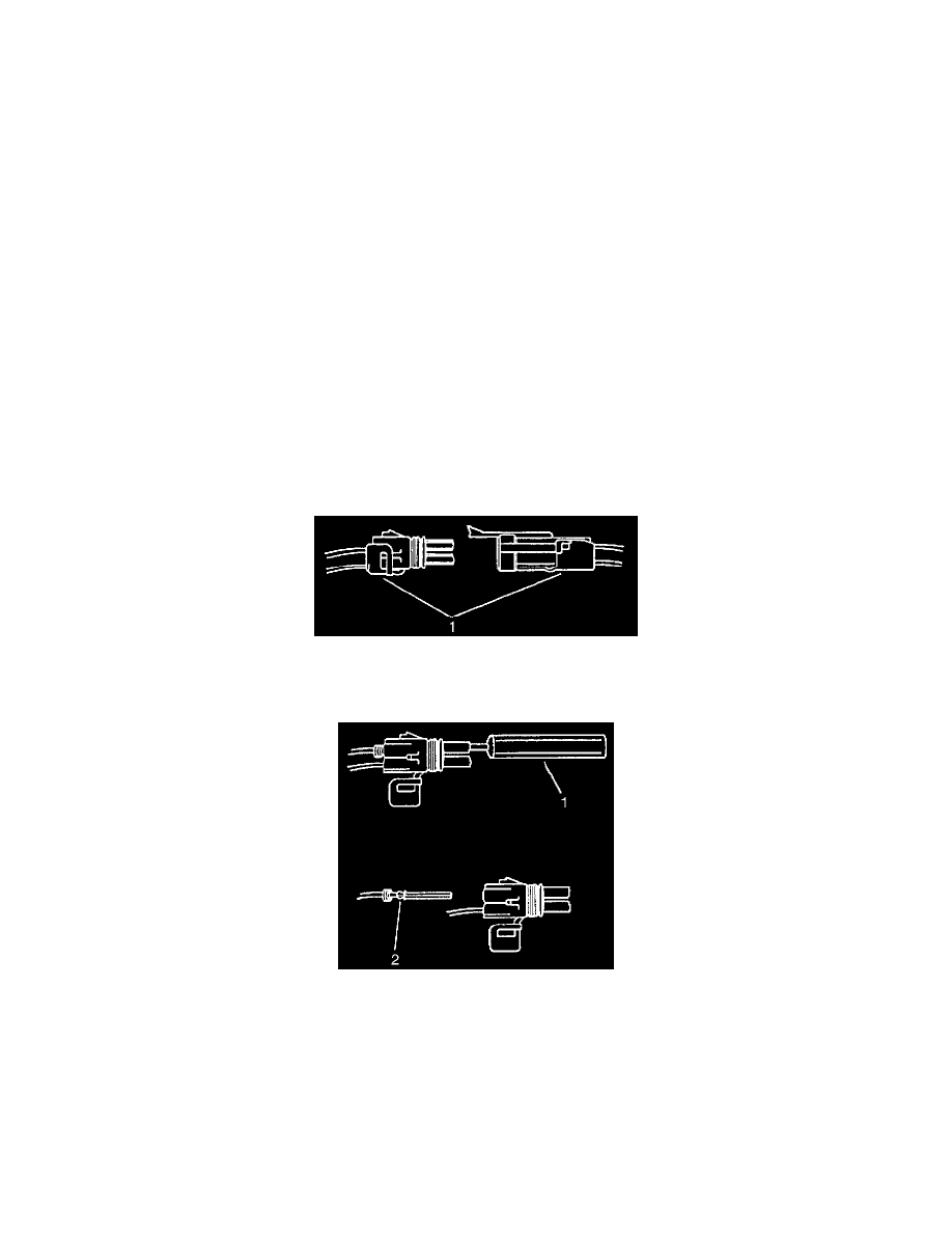
1. Separate the connector halves (1).
2. Open the secondary lock. A secondary lock aids in terminal retention and is usually molded to the connector (1).
3. Grasp the wire and push the terminal to the forward most position. Hold the wire in this position.
4. Insert the Weather Pack(R) terminal removal tool into the front (mating end) of the connector cavity until it rests on the cavity shoulder (1).
5. Gently pull on the wire to remove the terminal through the back of the connector (2).
IMPORTANT: Never use force to remove a terminal from a connector.
6. Inspect the terminal and connector for damage. Repair as necessary.
7. Reform the lock tang (2) and reset terminal in connector body.
8. Close secondary locks and join connector halves.
9. Verify that circuit is complete and working satisfactorily.
10. Perform system check.
Repairing Connector Terminals