
TrailBlazer 2WD V8-6.0L VIN H (2006)
Main Relay (Computer/Fuel System): Testing and Inspection
POWERTRAIN RELAY DIAGNOSIS
DIAGNOSTIC FAULT INFORMATION
Always perform the Diagnostic System Check - Vehicle prior to using this diagnostic procedure. See: Powertrain Management/Computers and Control
Systems/Testing and Inspection/Diagnostic Trouble Code Tests and Associated Procedures
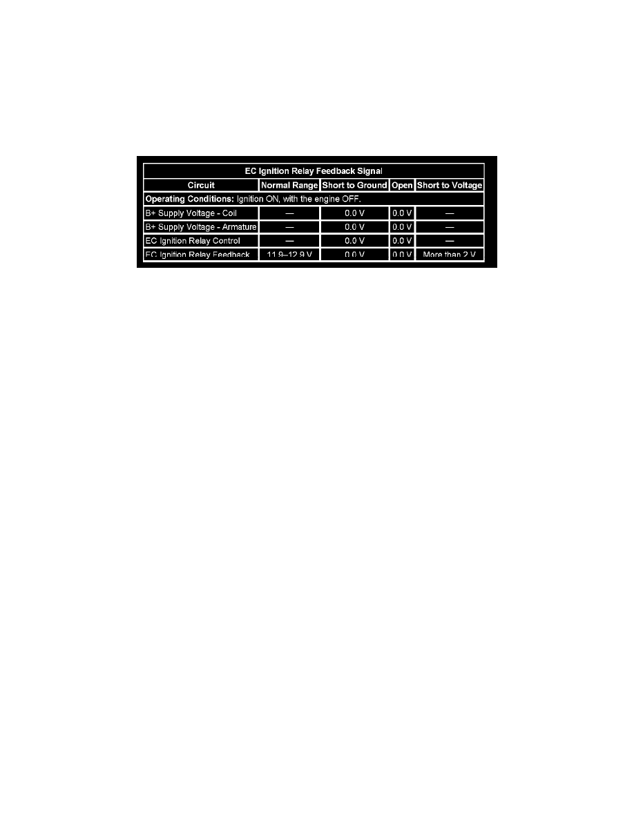
TYPICAL SCAN TOOL DATA
EC Ignition Relay Feedback Signal
CIRCUIT/SYSTEM DESCRIPTION
The powertrain relay is a normally open relay. The relay armature is held in the open position by spring tension. Battery positive voltage is supplied
directly to the relay coil and the armature contact at all times. The engine control module (ECM) supplies the ground path to the relay coil control
circuit via an internal integrated circuit called an output driver module (ODM). The ODM output control is configured to operate as a low side driver
for the powertrain relay. The ODM for the powertrain relay also incorporates a fault detection circuit, which is continuously monitored by the ECM.
When the ECM commands the powertrain relay ON, ignition 1 voltage is supplied to the following fuses in the underhood fuse block:
-
The ENG 1 fuse
-
The TAC fuse
-
The INJ A fuse
-
The INJ B fuse
-
The O2A fuse
-
The O2B fuse
The ignition 1 voltage that is supplied to the ECM through the TAC fuse, provides power to the internal ECM circuits associated with the throttle
actuator control (TAC) operation. The ECM also monitors the voltage level on the ignition 1 voltage circuit to confirm that the powertrain relay
contacts have closed.
DIAGNOSTIC AIDS
-
This test procedure requires that the vehicle battery has passed a load test and is completely charged. Refer to Battery Inspection/Test (Non-HP2).
-
When disconnecting electrical connectors or removing fuses and relays from a fuse block, always inspect the component electrical terminals for
corrosion and the mating electrical terminals for tightness.
-
Use the J 35616 Connector Test Adapter Kit for any test that requires probing the underhood fuse block terminals, component wire harness
terminals, or the ECM wire harness connector terminals.
CIRCUIT/SYSTEM VERIFICATION
1. With the ignition ON, engine OFF, command the powertrain relay ON and OFF several times using the scan tool output control function. You
should either hear or feel the relay click with each command.
2. With the ignition ON, engine OFF, probe both test points of each of the following fuses:
-
The ENG 1 fuse
-
The TAC fuse
-
The INJ A fuse
-
The INJ B fuse
-
The O2A fuse
-
The O2B fuse
-
The test lamp should illuminate on at least one test point of each fuse. If the test lamp does not illuminate, continue with Circuit/System
Testing.
CIRCUIT/SYSTEM TESTING
1. With the ignition OFF, remove the powertrain relay from the underhood fuse block.
2. With the ignition ON, measure for battery positive voltage (B+) between the relay coil voltage supply circuit and ground.
-
If the voltage measures less than B+, repair the open or high resistance in the circuit to the relay coil. All wire circuit resistance should measure