
Uplander AWD V6-3.5L VIN 8 (2005)
Ball Joint: Testing and Inspection
The content of this article reflects the changes identified in TSB Bulletin No.: 06-03-09-003
Date: May 15, 2006
SERVICE MANUAL UPDATE
Subject:
Revised Ball Joint Inspection Procedure and Independent Rear Suspension (IRS) Diagnosis Information
Models:
2002-2006 Buick Rendezvous
2005-2006 Buick Terraza
2001-2004 Chevrolet Venture (AWD)
2005-2006 Chevrolet Uplander (AWD)
2001-2004 Oldsmobile Silhouette (AWD)
2001-2004 Pontiac Montana (AWD)
2001-2005 Pontiac Aztek (AWD)
2005-2006 Pontiac Montana SV6 (AWD)
2005-2006 Saturn Relay (AWD)
Overview
Important:
This bulletin provides rear suspension information for 2001-2006 vans equipped with the independent rear suspension (IRS).
Rear ball joints should be inspected for end play, wear, or damage if one or more of the following repairs or conditions occur:
^
Prior to any repair procedure that requires the separation of the ball stud from the knuckle. For example, a knuckle, bearing, or axle shaft
replacement.
^
When a customer comments on rear suspension noises such as creaks, groans, pops, or rattles.
^
When a customer comments on irregular rear tire wear, or when a technician observes irregular rear tire wear.
^
Before checking or resetting the rear suspension alignment.
^
When investigating customer concerns about vehicle wandering or on-center handling.
Refer to Ball Joint Inspection (Rear Suspension - IRS) in SI or this bulletin.
Ball Joint Inspection (Rear Suspension - IRS)
1.
Raise and support the vehicle.
2.
Remove the rear tire and wheel assemblies.
3.
Perform a visual inspection of the ball joint seals for cuts or tears. If damage exists, replace the ball joint.
4.
Check wheel bearing for looseness.
5.
Remove the spring force from the lower control arm by supporting the lower control arm with a floor stand. Position the floor stand as far
outboard as possible and raise the control arm approximately 75 mm (3 in).
Important:
If the rotor does not have a hold down bolt, then install 3 lug nuts to ensure the stability of the rotor.
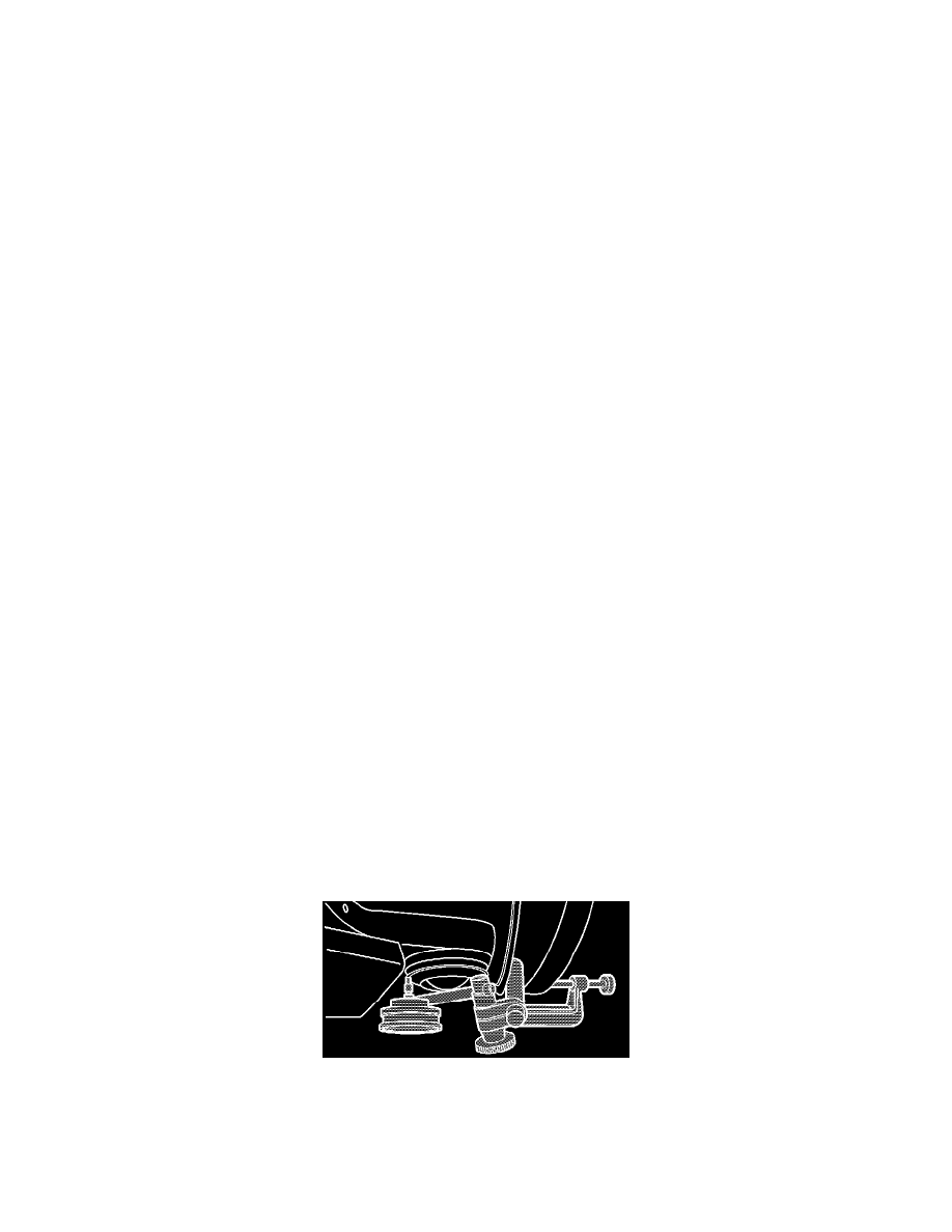
6.
Clamp the dial indicator J-8001 (or equivalent tool) to the bottom of the brake rotor. Place the dial indicator needle against the flange of the ball
joint at the ball joint centerline (most inboard point), as shown in the illustration.