
Uplander FWD V6-3.5L VIN L (2006)
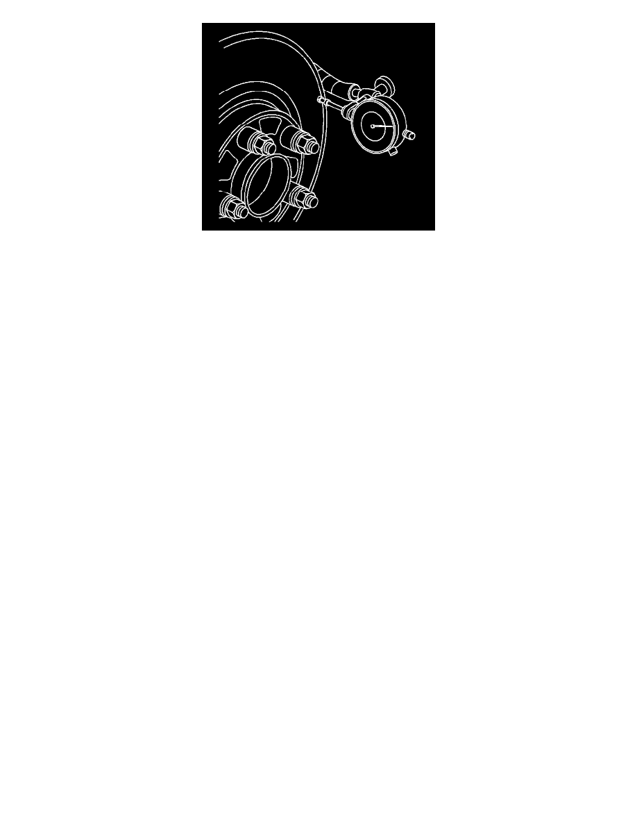
10. Mount a dial indicator, J 45101, or equivalent, to the steering knuckle and position the indicator button so it contacts the brake rotor friction
surface at a 90 degree angle, approximately 13 mm (0.5 inch) from the outer edge of the rotor.
11. Measure and record the assembled LRO of the brake rotor.
0. Rotate the rotor until the lowest reading is displayed on the indicator dial, then set the dial to zero.
1. Rotate the rotor until the highest reading is displayed on the dial.
2. Mark the location of the high spot relative to the nearest wheel stud, or studs.
3. Measure and record the amount of LRO.
12. Compare the brake rotor assembled LRO to the following specification:
^
Front brake rotor maximum allowable assembled lateral runout: 0.06 mm (0.002 inch)
^
Rear brake rotor maximum allowable assembled lateral runout: 0.06 mm (0.002 inch)
13. If the brake rotor assembled LRO is within specifications, proceed to step 18.If the brake rotor assembled LRO exceeds the specification, refinish
the rotor to ensure true parallelism, refer to Brake Rotor Refinishing. After refinishing the rotor, proceed to step 14. See: Brake Rotor Refinishing
14. Mount a dial indicator, J 45101, or equivalent, to the steering knuckle and position the indicator button so it contacts the brake rotor friction
surface at a 90 degree angle, approximately 13 mm (0.5 inch) from the outer edge of the rotor.
15. Measure and record the assembled LRO of the brake rotor.
0. Rotate the rotor until the lowest reading is displayed on the indicator dial, then set the dial to zero.
1. Rotate the rotor until the highest reading is displayed on the dial.
2. Mark the location of the high spot relative to the nearest wheel stud, or studs.
3. Measure and record the amount of LRO.
16. Compare the brake rotor assembled LRO to the following specification:
^
Front brake rotor maximum allowable assembled lateral runout: 0.06 mm (0.002 inch)
^
Rear brake rotor maximum allowable assembled lateral runout: 0.06 mm (0.002 inch)
17. If the brake rotor assembled LRO measurement exceeds the specification, bring the LRO to within specifications. Refer to Brake Rotor Assembled
Lateral Runout (LRO) Correction. See: Brake Rotor Assembled Lateral Runout Correction
18. If the brake rotor assembled LRO measurement is within specification, install the brake caliper and depress the brake pedal several times to secure
the rotor in place before removing the J 45101-100 and the lug nuts.
Brake Rotor Refinishing
Brake Rotor Refinishing
^
Tools Required
-
J 41013 Rotor Resurfacing Kit
-
J 42450-A Wheel Hub Resurfacing Kit
Caution: Refer to Brake Dust Caution in Service Precautions.
Important:
^
The disc brake rotors do not require refinishing as part of routine brake system service. New disc brake rotors do not require refinishing. Do not
refinish disc brake rotors in an attempt to correct the following conditions:
^
Brake system noise - squeal, growl, groan
^
Uneven and/or premature disc brake pad wear
^
Superficial or cosmetic corrosion/rust of the disc brake rotor friction surface
^
Scoring of the disc brake rotor friction surface less than the maximum allowable specification
^
Before refinishing a brake rotor, the rotor MUST first be checked for adequate thickness to allow the rotor to be refinished and remain above the
minimum allowable thickness after refinish specification. Refer to Brake Rotor Thickness Measurement. Disc brake rotors should only be
refinished if they have adequate thickness to be refinished and if one or more of the following conditions exist: See: Brake Rotor Thickness
Measurement