
Uplander FWD V6-3.5L VIN L (2006)
Body Control Module: Description and Operation
Power Mode
POWER MODE DESCRIPTION AND OPERATION
Power to many of this vehicle's circuits are controlled by the module that is designated the Power Mode Master (PMM). This vehicle's PMM is the Body
Control Module (BCM). The PMM controls which power mode (Run, Accessory, Crank, Retained Accessory Power, or Off) is active.
Serial Data Power Mode
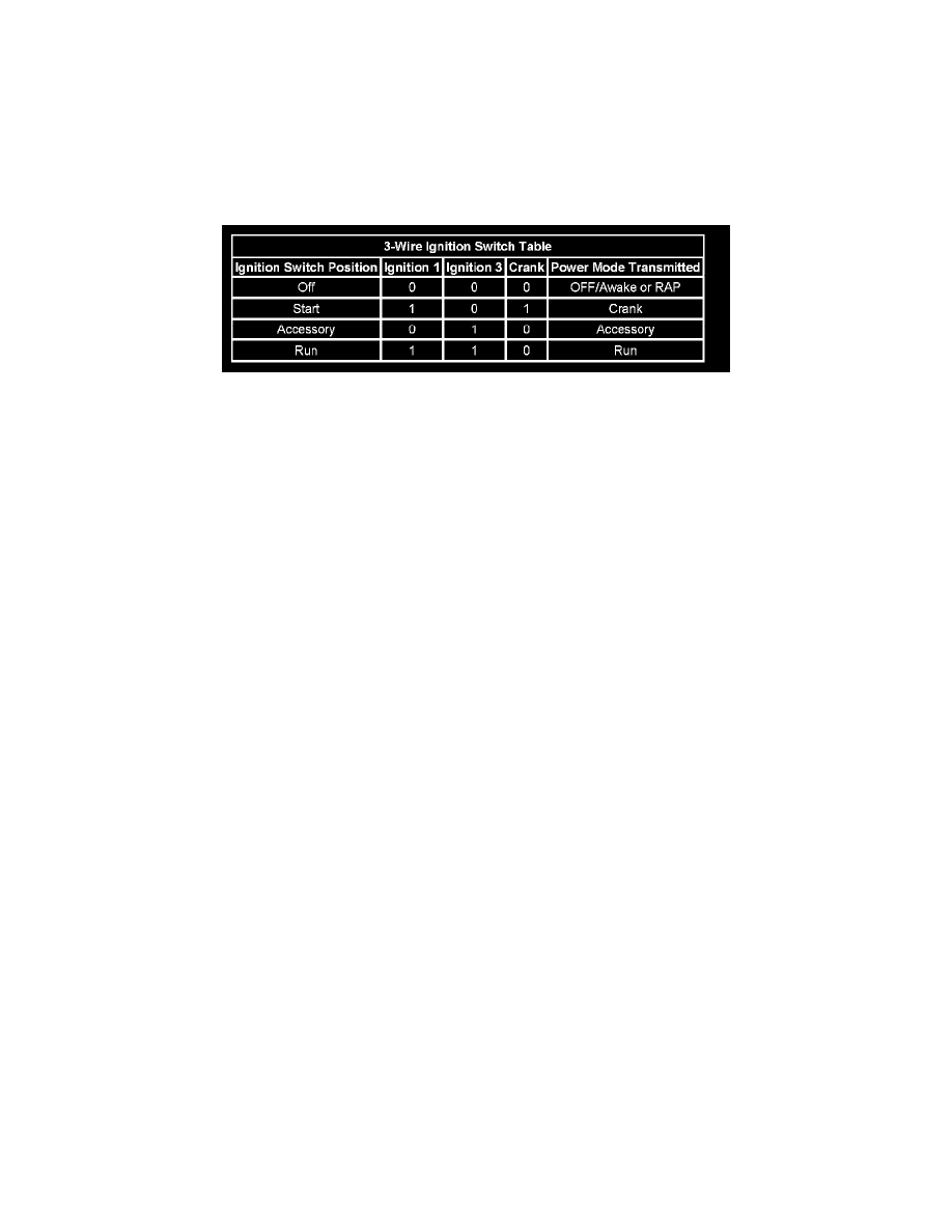
On vehicles that have several control modules connected by serial data circuits, one module is the power mode master (PMM). On this vehicle, the
PMM is the body control module (BCM). The PMM receives 3 discrete ignition switch signals to differentiate which power mode will be sent over the
Serial Data circuits. The table illustrates the state of these inputs in correspondence to the ignition switch position:
Relay Controlled Power Mode
The body control module (BCM) uses the discrete ignition switch inputs ignition 1, ignition 3 and crank to distinguish the correct power mode. Once
the BCM has determined the power mode selected by the vehicle operator it will energize the Ignition relay, Run relay and retained accessory power
(RAP) relay, depending on which power mode is selected.
Ignition 1 Relay
The relay uses a Hot At All Times B+ power source derived from the underhood electrical center. The ignition 1 relay supplies a power signal to the
following circuits when the Run or Crank power mode is selected:
-
AC clutch relay
-
ABS STG angle sensor
-
Antilock brake system (ABS) yaw sensor
-
Auxiliary power drop connector
-
Crank relay
-
Cruse control switch
-
Electronic brake control module (EBCM)
-
Engine control module (ECM)
-
HVAC module
-
Ignition control module (ICM)
-
Instrument panel cluster (IPC)
-
Sensing and diagnostic module (SDM)
-
Transmission solenoid circuit
Retained Accessory Power (RAP) Relay
The RAP relay is energized when the Run or Accessory power mode has been selected. The relay uses a Hot At All Times B+ power source derived
from the underhood electrical center. The B+ power source is protected by the 50 Amp BATT MAIN 2 fuse. The BCM also energizes the relay for 10
minutes after the vehicle operator transitions the ignition switch from Accessory to OFF or Run to OFF positions. The following circuits are
controlled by the RAP relay:
-
Power sunroof
-
Power windows
Fail-Safe Operation
Since the operation of the vehicle systems depends on the power mode, there is a fail-safe plan in place should the power mode master (PMM) fail to
send a power mode message. The fail-safe plan covers those modules using exclusively serial data control of power mode as well as those modules
with discrete ignition signal inputs.
Serial Data Messages
The modules that depend exclusively on serial data messages for power modes stay in the state dictated by the last valid PMM message until they can
check for the engine run flag status on the serial data circuits. If the PMM fails, the modules monitor the serial data circuit for the engine run flag
serial data. If the engine run flag serial data is True, indicating that the engine is running, the modules fail-safe to RUN. In this state the modules and
their subsystems can support all operator requirements. If the engine run flag serial data is False, indicating that the engine is not running, the modules
fail-safe to OFF-AWAKE. In this state the modules are constantly checking for a change status message on the serial data circuits and can respond to