
Uplander FWD V6-3.5L VIN L (2006)
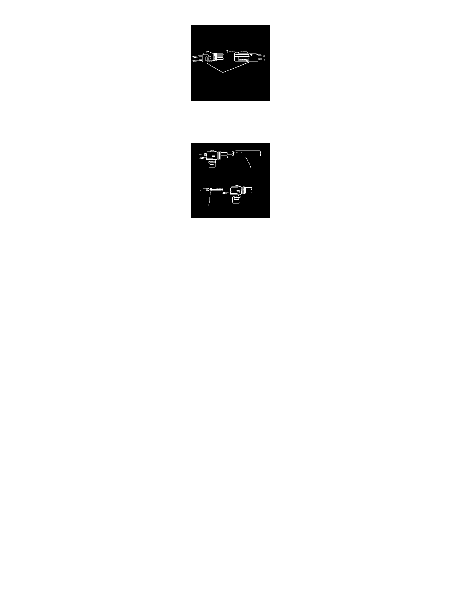
1. Separate the connector halves (1).
2. Open the secondary lock. A secondary lock aids in terminal retention and is usually molded to the connector (1).
3. Grasp the wire and push the terminal to the forward most position. Hold the wire in this position.
4. Insert the Weather Pack(R) terminal removal tool J 38125-10A (GM P/N 12014012-1) into the front (mating end) of the connector cavity until it
rests on the cavity shoulder (1).
5. Gently pull on the wire to remove the terminal through the back of the connector (2).
IMPORTANT: Never use force to remove a terminal from a connector.
6. Inspect the terminal and connector for damage. Repair as necessary.
7. Reform the lock tang (2) and reset terminal in connector body.
8. Close secondary locks and join connector halves.
9. Verify that circuit is complete and working satisfactorily.
10. Perform system check.
Repairing Connector Terminals
REPAIRING CONNECTOR TERMINALS
TOOLS REQUIRED
J-38125 Terminal Repair Kit
Use the following repair procedures in order to repair the following:
-
Push to Seat terminals
-
Pull to Seat terminals
Some terminals do not require all of the steps shown. Skip the steps that do not apply for your terminal repair. The J-38125 contains further
information.
1. Cut off the terminal between the core and the insulation crimp. Minimize any wire loss.For cable seal terminals, remove the seal.
2. Apply the correct cable seal per gage size of the wire, if used.Slide the seal back along the wire in order to enable insulation removal.
3. Remove the insulation.
4. For sealed terminals only, align the seal with the end of the cable insulation.
5. Position the strip in the terminal.For sealed terminals, position the strip and seal in the terminal.
6. Hand crimp the core wings.
7. Hand crimp the insulation wings.For sealed terminals, hand crimp the insulation wings around the seal and the cable.
8. Solder all of the hand crimp terminals excepting Micro-Pack 100 .64 size. Soldering Micro-Pack 100 World terminals may damage the terminal.
Terminal Position Assurance Locks
TERMINAL POSITION ASSURANCE LOCKS
The terminal position assurance (TPA) insert resembles the plastic combs used in the control module connectors. The TPA keeps the terminal securely
seated in the connector body. Do not remove the TPA from the connector body unless you remove a terminal for replacement.
Tyco/Amp Connectors (CM 42-Way)