
Venture AWD V6-3.4L VIN E (2004)
Crankshaft Position Sensor: Testing and Inspection
CRANKSHAFT POSITION SENSOR (CKP) SYSTEM DIAGNOSIS
CIRCUIT DESCRIPTION
The ignition system uses 2 different types of crankshaft position (CKP) sensors. The ignition control module (ICM) has independent power and
ground circuits. The CKP sensor B is used above 1650 RPM. The CKP sensor B provides the ICM with 7X signals. A signal converter within the
ICM produces digital 3X pulses to the powertrain control module (PCM). The 3X signal is passed to the PCM on the low resolution engine speed
signal circuit. The CKP sensor B is connected directly to the ICM, and consists of the following circuits:
-
The CKP sensor signal circuit
-
The low reference circuit
The CKP sensor A connects directly to the PCM, and consists of the following circuits:
-
The 12-volt reference circuit
-
The medium resolution engine speed signal circuit
-
The low reference circuit
The CKP sensor system diagnosis is used to diagnose a fault with CKP sensor B or any of the CKP sensor B circuits.
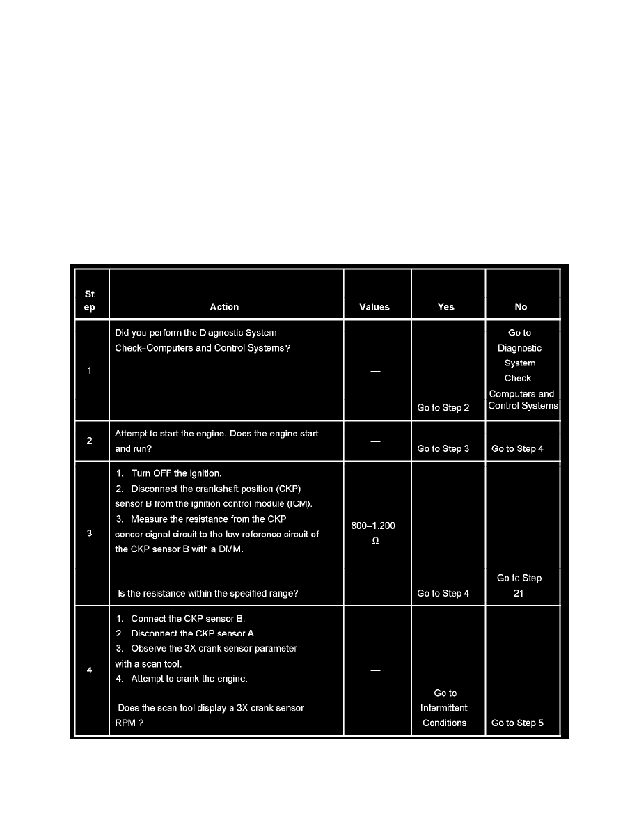
TEST
Steps 1-4