
300 SRT-8 V8-6.1L (2008)
-
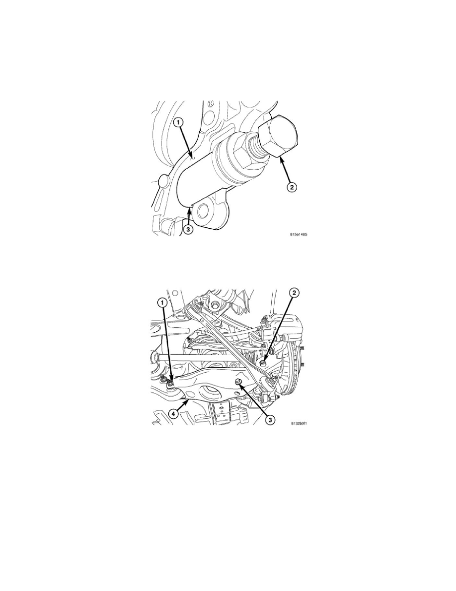
(3) Thrust Bearing
-
(4) Spherical Washer
-
(5) Sleeve 9361-9 (Left Side - Shown in figure)
-
(5) Sleeve 9361-10 (Right Side)
NOTE: When installing thrust bearing (3) on Remover, be sure to place hardened side against nut (2). Place bearing outer cage against
stationary component.
NOTE: It is important to use appropriate Sleeve (9361-9 or 9361-10) on Remover to provide proper Tool-to-Knuckle contact.
6. Thread Remover Bolt 9361-3 (2) into tapped knuckle sleeve.
7. Rotate Nut down, matching Sleeve (9361-9 or 9361-10) angled end with angled face of knuckle (1). Make sure foot on Sleeve (3) is inserted
behind machined brake caliper mounting boss.
8. Continue to rotate Nut until knuckle sleeve is removed from knuckle. Discard knuckle sleeve; replace it with new upon installation.
9. Remove bolt and nut (1) fastening spring link (4) to crossmember.
10. Remove spring link (4).
Spring Link
SPRING LINK