
300M V6-3.5L VIN G (2000)
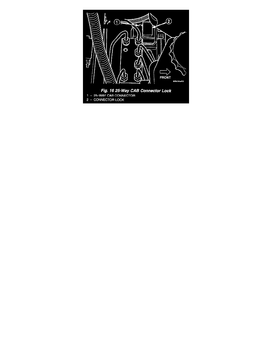
10. Disconnect the 25-way wiring harness connector from the CAB using the following procedure. Grasp the lock on the 25-way connector, and pull it
up from the connector as far as possible. This will unlock and raise the 25-way connector out of the socket on the CAB.
11. Raise vehicle on jackstands or centered on a hoist.
12. Remove the left front tire and wheel assembly.
13. Remove fasteners securing the inner fender splash shield in place. Move the splash shield out of the way.
14. Remove the 3 bolts attaching the ICU to the mounting bracket.
15. Remove the ICU from its mounting bracket Then, remove the ICU from the vehicle by pulling it out around the left side of the mounting bracket,
then through the wheel well.
INSTALLATION
1. Install the ICU back in the vehicle and attach it to its mounting bracket. Tighten the 3 ICU mounting bolts to 11 Nm (97 inch lbs.).
2. Reinstall the inner fender splash shield.
3. Reinstall the tire and wheel assembly.
4. Lower the vehicle.
CAUTION: Before installing the 25-way connector in the CAB, be sure that the seal is properly installed in the connector.
5. Install the 25-way connector into the socket on the CAB. The connector is installed using the following procedure. Position the 25-way connector
in the socket on the CAB and carefully push it onto CAB as far as it will go. When connector is fully seated into the CAB socket push in the
connector lock as far as it will go. This will pull the 25-way connector into the socket on the CAB and lock it in the installed position.
6. Install the 4 chassis brake tubes on the HCU. Tighten the chassis brake tubes to 17 Nm (145 inch lbs.).
7. Install the primary and secondary brake lines from the master cylinder on the HCU. Tighten the primary and secondary brake tubes to 17 Nm (146
inch lbs.).
8. Reinstall the transmission controller.
9. Reattach the washer bottle filler neck to the radiator support.
10. Reinstall the speed control servo to its mounting studs and radiator support.
11. Remove brake pedal positioning tool.
12. Install the remote ground cable onto the ground stud located on left shock tower. Install the remote ground cable attaching nut and tighten to a
torque of 28 Nm (250 inch lbs.).
NOTE: The ICU may need to be initialized, using the DRB scan tool, after installation.
13. Bleed the base brakes and the ABS brakes hydraulic system.
14. Road test vehicle to ensure proper operation of the base and ABS systems.