
300M V6-3.5L VIN G (2000)
Controller Antilock Brake: Description and Operation
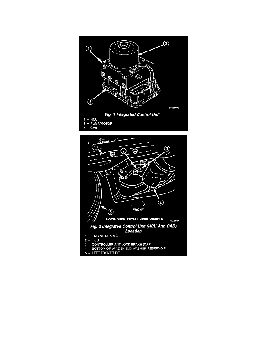
INTEGRATED CONTROL UNIT (ICU)
DESCRIPTION
The Hydraulic Control Unit (HCU) and the Controller Antilock Brake (CAB) used with this antilock brake system are combined (integrated) into one
unit, which is called the Integrated Control Unit (ICU). The ICU is located in front of the driver's side front tire, behind the inner fender splash shield.
Two different ICU's (HCU and CAB) are used on this vehicle depending on whether or not the vehicle is equipped with traction control. The HCU on
a vehicle equipped with traction control has a valve block that is approximately one inch longer than a HCU on a vehicle that is equipped with ABS
only.
The ABS-only ICU consists of the following components: the CAB, eight (build/decay) solenoid valves (four inlet valves and four outlet valves),
valve block, fluid accumulators, a pump, and an electric motor.
The ABS-with traction control ICU consists of the following components: the CAB, eight (build/decay) solenoid valves (four inlet valves and four
outlet valves), two traction control (ASR) valves, two hydraulic shuttle valves, valve block, fluid accumulators, a pump, and an electric motor.
The replaceable components of the ICU are the HCU and the CAB. No attempt should be made to service any individual components of the HCU or
CAB.
OPERATION
^
CONTROLLER ANTILOCK BRAKE (CAB)