
300M V6-3.5L VIN G (2000)
Brake Proportioning/Combination Valve: Testing and Inspection
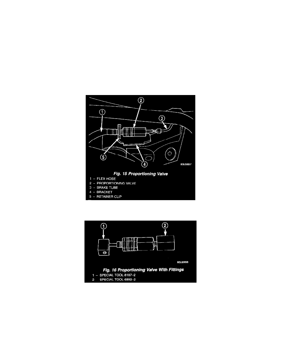
PROPORTIONING VALVE TEST (WITH AND WITHOUT ANTILOCK BRAKES)
CAUTION: Not all components use the same type tubing flare. The tube leading into the proportioning valve has an ISO flare, while the flex hose
coming out of the proportioning valve has a standard double-inverted flare. Use the correct adapters when installing gauges to test proportioning valves.
Both vehicles, with Antilock Brakes, and without Antilock Brakes, have two proportioning valves. One valve is connected to each rear flex hose. One
proportioning valve controls the right rear brake, and the other proportioning valve controls the left rear brake.
On vehicles without ABS, if premature wheel skid occurs on a hard brake application, it could be an indication that a malfunction has occurred with
one of the two rear brake proportioning valves. Test the valve that controls the side of the vehicle on which the skid occurs.
On vehicles with ABS, if premature rear wheel ABS cycling occurs on a hard brake application, it could be an indication that a malfunction has
occurred with one of the two proportioning valves. Since ABS cycles both rear brakes together, both valves must be tested to isolate the suspect
proportioning valve.
1. Raise the vehicle on jack stands or centered on a hoist.
2. Clean any debris away from the suspect proportioning valve, connections, and area.
3. Remove the chassis brake tube from the suspect proportioning valve.
4. Remove the proportioning valve from the rear flex hose which is held stationary by a bracket mounted on the back side of the crossmember.
5. Remove the retainer clip securing the rear flex hose from its bracket. This should be done to allow the proportioning valve pressure test fittings to
be installed without bending the chassis brake tube.
CAUTION: Be sure the pressure test fittings being installed into the proportioning valve, have the correct thread sizes for installation into the
proportioning valve and installation of the chassis brake tubes.
6. Correctly install Pressure Test Fittings, Special Tool 6892-2 into the inlet port, and Special Tool 8187-2 into the outlet port, of the proportioning
valve.
7. Install the proportioning valve and the Pressure Test Fittings, Special Tool 6892-2 and 8187-2, as an assembly back into the chassis brake tube.
Connect Special Tool 6892-2 to the chassis brake tube, and Special Tool 8187-2 to the brake flex hose.