
300M V6-3.5L VIN G (2000)
CONTROLLER ANTILOCK BRAKE OUTPUTS
^
amber ABS warning lamp actuation (via BUS)
^
instrument cluster (MIC) communication (PCI)
^
traction control lamps (if equipped)
^
diagnostic communication (PCI, via BUS)
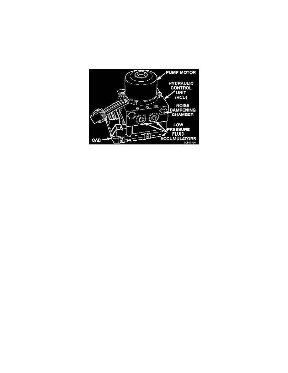
HYDRAULIC CONTROL UNIT (HCU)
DESCRIPTION
Teves Mark 20 ICU
The Hydraulic Control Unit (HCU) is mounted to the CAB as part of the ICU. The ICU is located in front of the driver's side front tire, behind the
inner fender splash shield. The HCU controls the flow of brake fluid to the brakes using a series of valves and accumulators. A pump/motor is
mounted on the HCU to supply build pressure to the brakes during an ABS stop.
The HCU on a vehicle equipped with traction control has a valve block that is approximately one inch longer than a HCU on a vehicle that is equipped
with ABS only in order to incorporate the additional valves.
OPERATION
The operation of the HCU's hydraulic circuits can be found in Brakes, Antilock Brake System, Description And Operation, Hydraulic Circuits And
Valve Operation.
The following topics explain how the different components within the HCU operate.
VALVES AND SOLENOIDS
The valve block contains four inlet valves and four outlet valves. The inlet valves are spring-loaded in the open position and the outlet valves are
spring loaded in the closed position during normal braking.
The fluid is allowed to flow from the master cylinder to the wheel brakes.
During an ABS stop, these valves cycle to maintain the proper slip ratio for each wheel. The inlet valve closes preventing further pressure increase and
the outlet valve opens to provide a path from the wheel brake to the HCU accumulators and pump/motor. This releases (decays) pressure from the
wheel brake, thus releasing the wheel from excessive slippage. Once the wheel is no longer slipping, the outlet valve is closed and the inlet valve is
opened to reapply (build) pressure.
For information on the valves used with the traction control system, refer to Traction Control System, Description and Operation.
BRAKE FLUID ACCUMULATORS