300M V6-3.5L VIN G (2000)

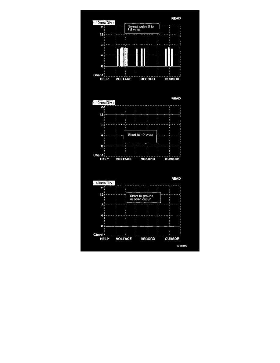
The Chrysler Programmable Communication Interface multiplex system (PCI bus) consists of a single wire. The Body Control Module (BCM)
acts as a splice to connect each module and the Data Link Connector (DLC) together. Each module is wired in parallel to the data bus through its
PCI chip set and uses its local ground as the bus reference. The wiring is a minimum 20 gage. The PCI bus wire insulation color will be yellow
with a violet tracer. An extra tracer color may be added along with the violet to help distinguish between different node connections.
The bus is designed to handle a maximum number of nodes to meet all of the bus load and timing requirements. The bus resistance and
capacitance is designed to provide a maximum level of filtering without distorting the bus symbols. This is why extra capacitance and resistance
should not be added to the PCI Data Bus circuitry.
In order for an electronic control module to communicate on the PCI data bus, the module must have bus interface electronics consisting of a
transmitter/receiver (or transceiver) and Logic control, bus termination for loading and filtering the bus, and wiring which interconnects the
system.
Because of the unique coding scheme used in the PCI bus, each module is required to have logic control. The data moving on the bus is called
symbols. The interface logic performs the following functions: encode and decodes binary data into symbols, synchronizes all bus symbol timing
and edges, controls the sending and receiving of messages, monitors for bus arbitration, monitors for corrupted symbols due to noise and controls
the transceiver.
