
300M V6-3.5L VIN G (2000)
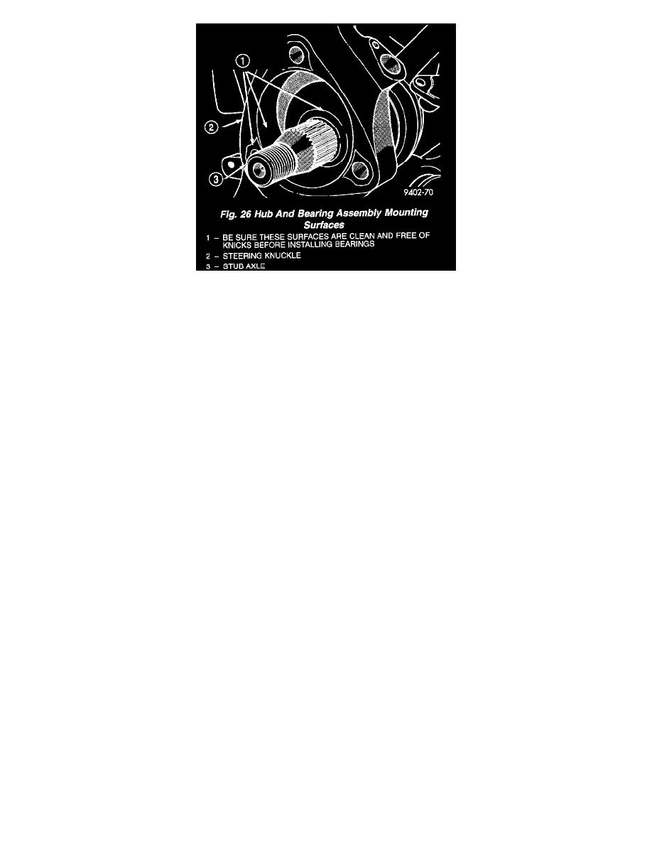
CAUTION: Hub and bearing assembly mounting surfaces on steering knuckle and halfshaft must be smooth and completely free of foreign
material or nicks. When installing hub and bearing assembly into steering knuckle, be careful not to damage the flinger discon hub and bearing
assembly. If flinger disc becomes damaged, hub and bearing assembly MUST not be used and MUST be replaced with a new hub and bearing
assembly.
4. Install hub and bearing assembly onto stub shaft and into steering knuckle until squarely seated on face of steering knuckle.
5. Install the 3 steering knuckle to hub and bearing assembly attaching bolts. Equally tighten all 3 mounting bolts until hub and bearing assembly is
squarely seated against front of steering knuckle. Then tighten all 3 hub and bearing assembly mounting bolts to a torque of 110 Nm (80 ft. lbs.).
CAUTION: The hub and bearing assembly to stub shaft retaining nut is a prevailing torque nut and can not be reused. A NEW retaining nut
MUST be used when assembled.
6. Install a NEW hub and bearing assembly to stub shaft retaining nut. Tighten, but do not torque the hub nut at this time.
7. Coat speed sensor head with High Temperature Multipurpose E. P. Grease before installing into the steering knuckle. Install speed sensor head
into steering knuckle. Install screw and tighten to a torque of 7 Nm (60 inch lbs.).
8. Install the braking disk back on the hub and bearing assembly.
9. Install front brake caliper on steering knuckle. Refer to Front Disc Brake Service in Brakes and Traction Control for caliper installation procedure.
Install the caliper to steering knuckle attaching bolts and tighten them to a torque of 19 Nm (168 inch lbs.).
10. Install wheel and tire assembly on vehicle. Tighten the wheel mounting stud nuts in proper sequence until all nuts are torqued to half specification.
Then repeat the tightening sequence to the full specified torque of 129 Nm (95 ft. lbs.).
11. Lower vehicle to the ground.
CAUTION: When torquing hub and bearing assembly to stub shaft retaining nut, do not exceed the maximum torque of 163 Nm ± 14 Nm (120
ft. lbs. ± 10 ft. lbs.). If the maximum torque is exceeded this may result in a failure of the drive shaft.