
300M V6-3.5L VIN G (2000)
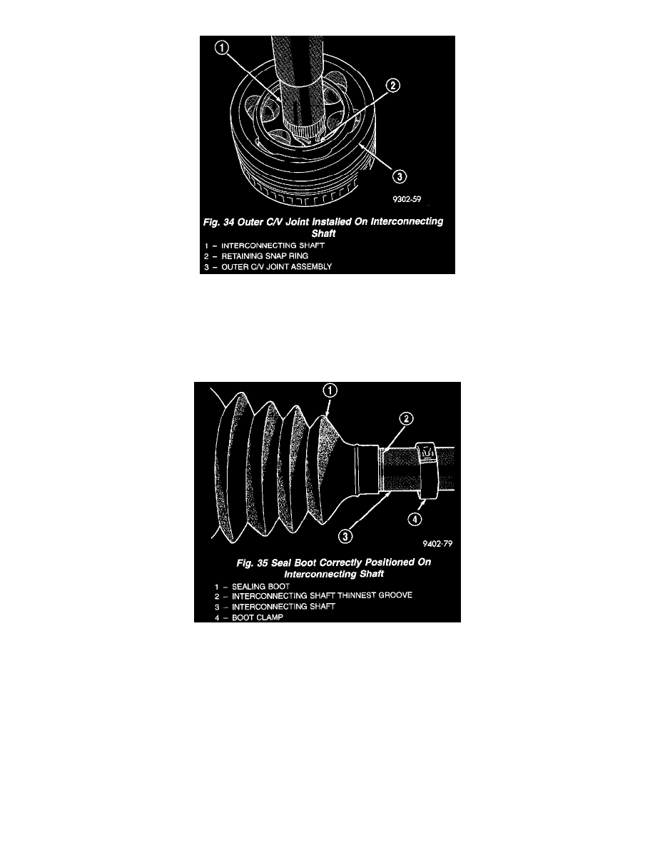
Fig. 34
2. Install outer C/V joint assembly onto interconnecting shaft. Joint is installed on interconnecting shaft, by pushing interconnecting shaft into outer
C/V joint, until retaining snap ring is seated in groove on interconnecting shaft (Fig. 34). Verify the snap ring is fully seated into groove on
interconnecting shaft.
3. Distribute 1/2 the amount of grease provided in seal boot service package (DO NOT USE ANY OTHER TYPE OF GREASE) into outer C/V joint
assembly housing. Put the remaining amount into the sealing boot.
Fig. 35
4. Install outer C/V joint seal boot retaining clamp, onto interconnecting shaft. Install replacement outer C/V joint sealing boot onto interconnecting
shaft. Outer C/V joint seal boot MUST be positioned on interconnecting shaft, so only the thinnest (sight) groove on interconnecting shaft is
visible (Fig. 35).