
Aspen 4WD V8-5.7L Hybrid (2009)
3. Install companion flange on the end of the shaft with the reference marks aligned.
4. Install two bolts into the threaded holes in the companion flange, 180° apart.
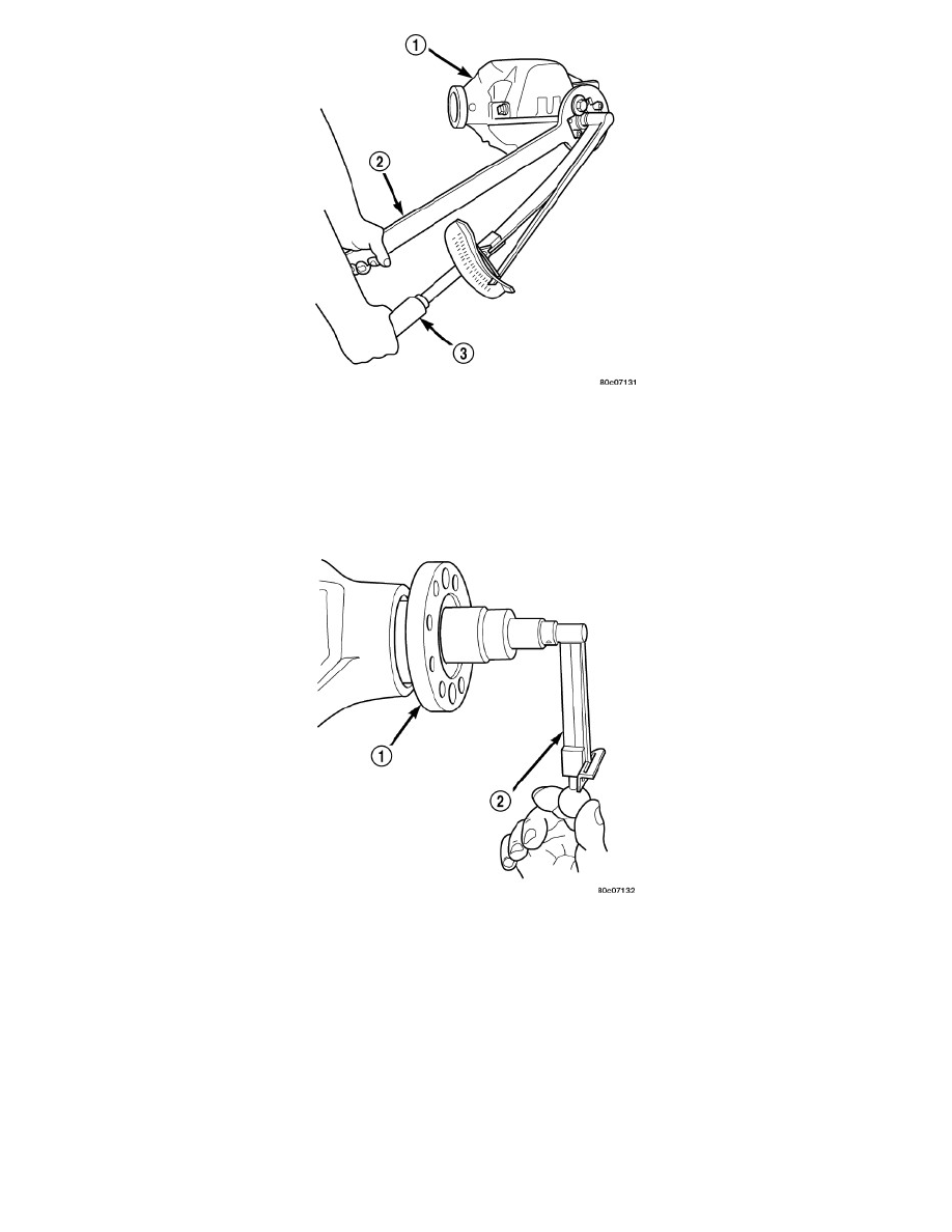
5. Position Holder 6719A (2) against the companion flange and install a bolt and washer into one of the remaining threaded holes. Tighten the bolts
so holder is held to the flange.
6. Install companion flange on pinion shaft with Installer C-3718 and Holder 6719A.
7. Install pinion washer and a new pinion nut. The convex side of the washer must face outward.
8. Hold companion flange with Holder 6719A (2) and tighten pinion nut with a torque wrench (3) to 285 Nm (210 ft. lbs.).NOTE: Do not exceed
the minimum torque 285 Nm (210 ft. lbs.) when installing the pinion nut at this point.
9. Rotate pinion several times to ensure pinion bearings are seated.
10. Measure pinion torque to rotate (1) with an inch pound torque wrench (2). Pinion torque to rotate should be equal to recorded reading plus an
additional 0.56 Nm (5 in. lbs.).
If pinion torque to rotate is low, tighten pinion nut in 6.8 Nm (5 ft. lbs.) increments until pinion torque to rotating is achieved.
CAUTION: Never loosen pinion nut to decrease pinion bearing rotating torque. If pinion torque to rotating is exceeded, a new collapsible
spacer must be installed. Failure to follow these instructions will result in damage to the axle.
11. Install propeller shaft.
12. Install rear brake rotors components.