
Aspen 4WD V8-57L Hybrid Wiper Motor Removal - Service and Repair
Wiper Motor: Service and Repair
Wiper Motor - Installation
Front
FRONT
CAUTION: Do not apply pressure to, or pry on, the plastic drive link bushing. When removing the drive link from, or installing the drive link
to the ball stud on the wiper motor crank arm, apply pressure to, or pry on, only the metal portions of the drive link around the
bushing. If the bushing is damaged, the entire front wiper module MUST be replaced.
CAUTION: Do not remove the crank arm nut from the wiper motor output shaft. The crank arm is indexed to the output shaft with the motor
in the park position during the manufacturing process, but there are no provisions made for correctly indexing this connection in
the field. If the crank arm to output shaft indexing is incorrect, the entire front wiper module MUST be replaced.
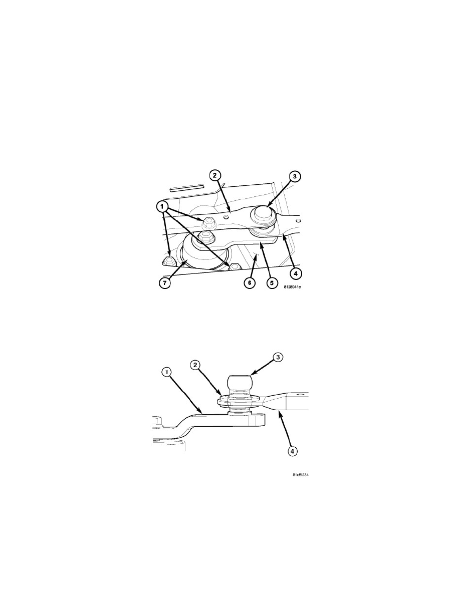
1. Position the front wiper motor (7) and crank arm (5) unit to the front wiper module bracket (6) from the underside of the bracket.
2. Install and tighten the three screws (1) that secure the motor to the bracket. Tighten the screws to 7 Nm (62 in. lbs.).
3. Position the left wiper drive link (4) sleeve bushing (2) over the ball stud (3) on the end of the motor crank arm (1).
4. Place a short 19 millimeter or 3/4 inch socket over the sleeve bushing as an installation tool. Then use large channel-lock pliers to apply enough
pressure to the underside of the crank arm and the top of the socket to snap the bushing over the upper ball and onto the lower ball of the ball stud.
Do not apply pressure directly to the plastic bushing and do not press the bushing beyond the lower ball of the ball stud.
CAUTION: Carefully inspect the installed sleeve bushing (2) to be certain it is centered over the lower ball of the ball stud (3), and not trapped
between the lower ball and the crank arm (1). There should be a visible clearance between the lower surface of the sleeve bushing
and the crank arm. Refer to the accompanying illustration. The sleeve bushing must be able to swivel freely on the lower ball
during wiper operation. If the bushing is trapped between the lower ball and the crank arm, the bushing and the drive link (4)
may be damaged.