
Cirrus V6-2.5L VIN H (1995)
Body Control Module: Customer Interest
Gauges - Freeze or Zero Intermittently
NO: 08-19-95
GROUP: Electrical
DATE: Apr. 28, 1995
SUBJECT:
Gauges Zero or Freeze Intermittently
MODELS:
1995 (JA) Cirrus/Stratus
SYMPTOM/CONDITION:
Speedometer/tachometer/fuel gauge indicators may go to zero or freeze intermittently.
DIAGNOSIS:
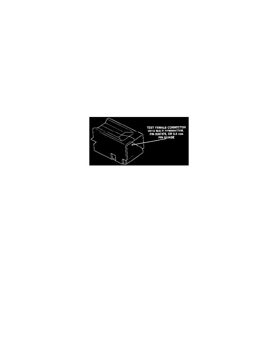
Condition may be too intermittent to duplicate or cannot be found by routine diagnostic methods. Inspect the D1 and D2 female terminals in the 14-way
(black) and 22-way (white) body control module connectors. Use a 0.6 mm pin gauge or male terminal, P/N 5267475, to determine it female terminal is
spread (opened too large). If any of the terminals are spread, perform the repair procedure.
PARTS REQUIRED:
AR
4798869
Wiring Terminal Kit
1
5267475
Terminal, Male
NOTE:
WIRING TERMINAL KIT, P/N 4798869, CONTAINS A TERMINAL ASSEMBLY AND HEAT SHRINK TUBING NECESSARY TO
REPLACE ANY DAMAGED TERMINAL IN THE 14-WAY BLACK, 22-WAY WHITE, 20-WAY BLACK OR 10-WAY WHITE BODY
CONTROL MODULE CONNECTORS.
REPAIR PROCEDURE:
This bulletin involves replacing a damaged (spread) wiring terminal.
1.
Record the preset radio stations. Disconnect and isolate the battery negative cable.
2.
Disconnect the connector being repaired.
3.
Remove or open the connector locking wedge.
4.
Position the connector locking finger away from the terminal using the proper pick Special Tool # 6932. Pull on the wire to remove the terminal
from the connector.
5.
Cut the wire 6 inches from the back of the connector.
6.
Remove 1 inch of insulation from the wire on the harness side and new terminal assembly.
7.
Place heat shrink tubing over wire.
8.
Spread the strands of the conductor apart on each part of the exposed wires.
9.
Push the two ends of wire together until the strands of conductor are close to the insulation.
10.
Twist the conductors together.
11.
Solder the conductors together using rosin core solder only. Do not use acid core solder.
12.
Center the heat shrink tubing over the joint and heat using a heat gun. Heat the joint until the tubing is tightly sealed and sealant comes out of both
ends of the tubing.
13.
Insert the new terminal into the connector.
14.
Install the locking wedge and connector into control module.