
Cirrus V6-25L VIN H (1995) Intake Manifold Cleaning and Inspection
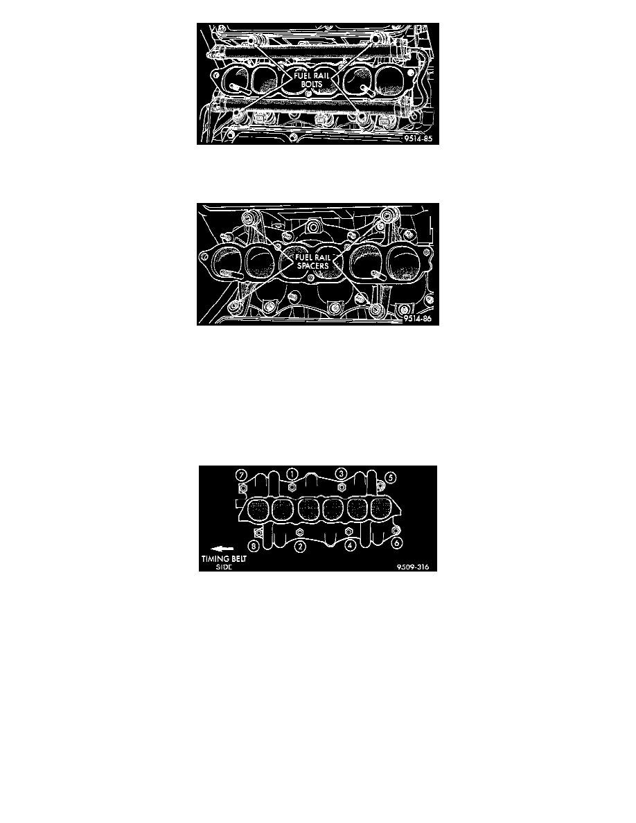
Fig. 9 Fuel Rail Attachment
17. Remove 4 bolts holding fuel rail Fig. 9.
Fig. 10 Fuel Rail Spacers
18. Lift fuel rail off engine. There are spacers under each fuel rail bolt Fig. 10.
19. Remove lower intake manifold attaching bolts. Remove intake manifold.
CLEANING AND INSPECTION
1. Discard gasket and clean all gasket surfaces of manifold to cylinder heads.
2. Check upper and lower manifold gasket surfaces for flatness with straight edge. Surface must be flat within 0.15 mm per 300 mm (0.006 in. per
foot) of manifold length.
3. Inspect manifolds for cracks or distortion. Replace manifold if necessary.
Fig. 11 Intake Manifold Tightening Sequence
INSTALLATION
1. Install intake manifold with new gaskets. Tighten in sequence shown in Fig. 11 to 28 Nm (250 in. lbs.).
2. Apply a light coating of clean engine oil to the 0-ring on the nozzle end of each injector.
3. Insert fuel injector nozzles into openings in intake manifold. Seat the injectors in place. Tighten fuel rail bolts to 12 Nm (8 ft. lbs.).
4. Attach electrical connectors to fuel injectors.
5. Connect fuel supply tube to fuel rail.
6. Install new gasket and position upper intake plenum. Tighten plenum bolts to 18 Nm (13 ft. lbs.) torque.
7. Install bolts at plenum support brackets. Tighten bolts to 18 Nm (13 ft. lbs.).
8. Install EGR tube to plenum. Tighten EGR tube to intake manifold plenum screws to 11 Nm (95 in. lbs.) torque.
9. Install throttle cables.
10. Attach electrical connectors to sensors.
11. Tighten air inlet tube clamps to 3 ± 1 Nm (25 ± 5 in. lbs.).
12. Connect negative terminal to auxiliary jumper terminal Fig. 2.