
Cirrus V6-2.5L VIN H (1995)
Canister Purge Solenoid: Description and Operation
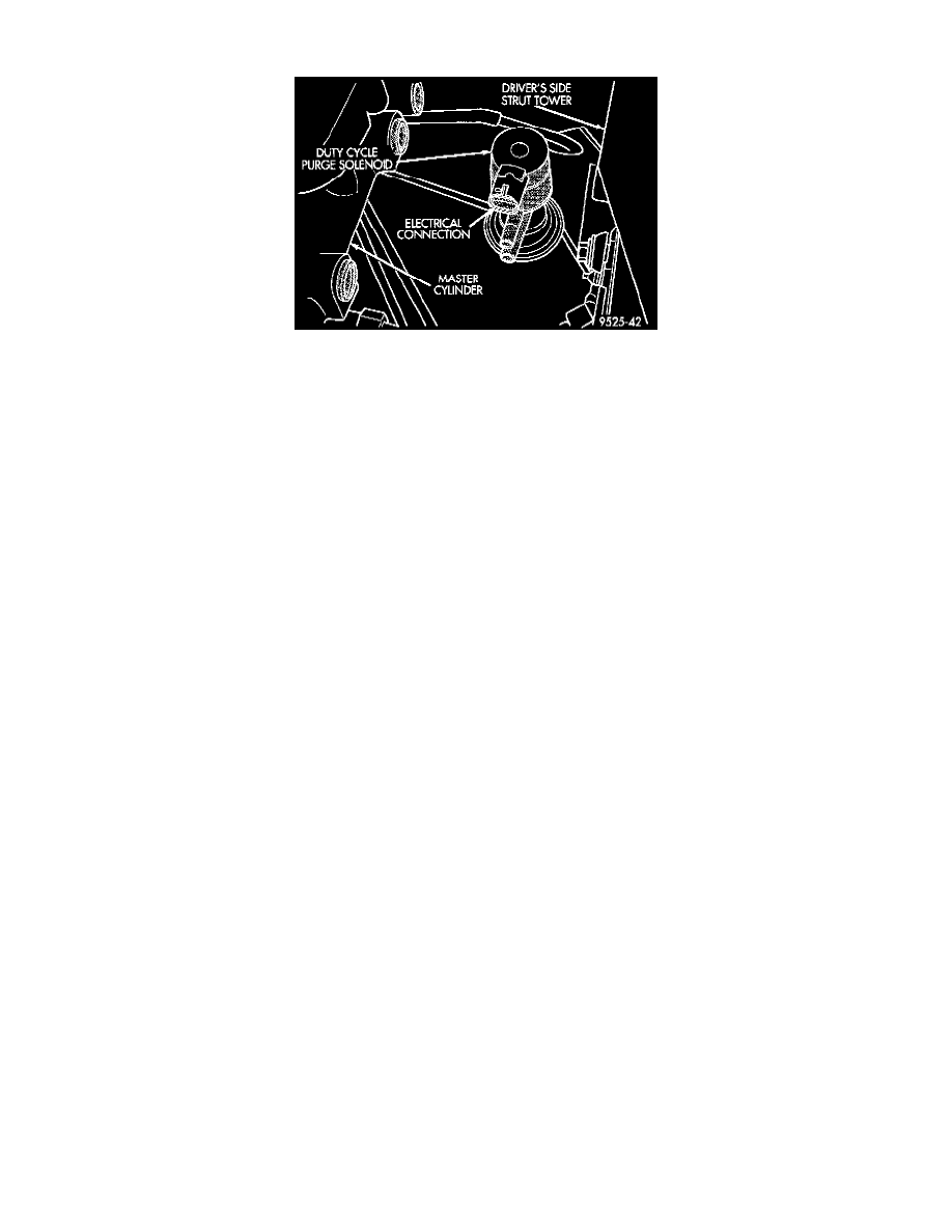
Fig. 26 Duty Cycle EVAP Purge Solenoid
PURPOSE
The duty cycle EVAP purge solenoid regulates the rate of vapor flow from the EVAP canister to the throttle body. The PCM operates the
solenoid.
OPERATION
During the cold start warm-up period and the hot start time delay the PCM does not energize the solenoid. When de-energized, no vapors are
purged.
The engine enters closed loop operation after it reaches a specified temperature and the programmed time delay ends. During closed loop
operation, the PCM energizes and de-energizes the solenoid 5 to 10 times per second, depending upon operating conditions. The PCM varies the
vapor flow rate by changing solenoid pulse width. Pulse width is the amount of time the solenoid is energized.
The solenoid attaches to a bracket on the driver's side strut tower Fig. 26. To operate correctly, the solenoid must be installed with the electrical
connector on top.
CIRCUIT OPERATION
Circuit F18 supplies battery voltage to the duty cycle EVAP/Purge solenoid. This circuit is HOT in the START and RUN position only. It is also
spliced and provides power for the Anti-Lock warning lamp, A/C clutch relay, and high speed radiator fan relay.
Circuit F18 connects to the PDC, cavity 9, and is protected by a 10 amp fuse. Power for the fuse is supplied on circuit A21 from the ignition
switch. Circuit A1 provides power for the A21 circuit and is protected by a 20 amp fuse located in cavity 8 of the Power Distribution Center
(PDC).
The Powertrain Control Module (PCM) controls the ground path for the solenoid on circuit K52. Circuit K52 connects to cavity 68 of the PCM
connector.