
Cirrus V6-2.5L VIN H (1995)
Oxygen Sensor: Description and Operation
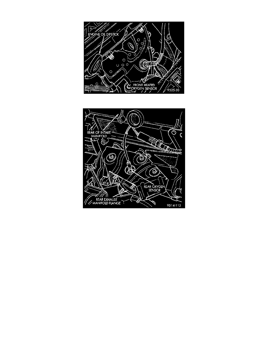
Fig. 17 Front Heated Oxygen Sensor
Fig. 18 Rear Heated Oxygen Sensor
HEATED OXYGEN SENSORS - PCM INPUT
The input from the upstream heated oxygen sensor tells the PCM the oxygen content of the exhaust gas. Based on this input, the PCM fine tunes
the air-fuel ratio by adjusting injector pulse width.
The sensor input switches from 0 to 1 volt, depending upon the oxygen content of the exhaust gas in the exhaust manifold. When a large amount of
oxygen is present (caused by a lean air-fuel mixture), the sensor produces voltage as low as 0.1 volt. When there is a lesser amount of oxygen
present (rich air-fuel mixture) the sensor produces a voltage as high as 1.0 volt. By monitoring the oxygen content and converting it to electrical
voltage, the sensor acts as a rich-lean switch.
The heating element in the sensor provides heat to the sensor ceramic element. Heating the sensor allows the system to enter into closed loop
operation sooner. Also, it allows the system to remain in closed loop operation during periods of extended idle.
In Closed Loop, the PCM adjusts injector pulse width based on the upstream heated oxygen sensor input along with other inputs. In Open Loop,
the PCM adjusts injector pulse width based on preprogrammed (fixed) values and inputs from other sensors.
The upstream oxygen sensor threads into the outlet flange of the exhaust manifold Fig. 17 and 18.
CIRCUIT OPERATION
Circuit A14 is connected to the BUS bar in the Power Distribution Center (PDC), which connects to battery voltage. The contact side of the
Automatic Shut-Down (ASD) relay connects circuit A14 and circuit A142. A 20 amp fuse, located in cavity 5 of the PDC, protects circuits A14
and A142.