
Cirrus V6-2.5L VIN H (1995)
Clockspring Assembly / Spiral Cable: Service and Repair
REMOVAL
WARNING: When removing a deployed module, rubber gloves, eye protection and long sleeves should be worn. There may be deposits on the
surface which could irritate the skin and eyes.
1. Disconnect and isolate the battery negative remote cable.
2. Remove the two steering column lower cover attaching screws. Remove upper cover.
3. Remove the Driver Airbag Module attaching T-30 Torx bolts from back side of the steering wheel. Lift the module and disconnect the wire by:
a. Lifting the secondary latch.
b. Disconnect the connector from back of the airbag module using the finger grips. Use care not to pull on wires. Never use a metallic tool to pry
on the connector.
4. Remove the speed control switch screws from back of the steering wheel. Pull the switch pods out and disconnect the wires.
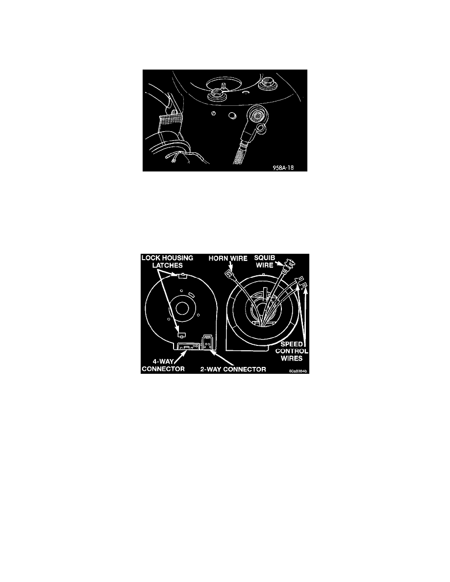
5. Disconnect the horn wire from the steering wheel and remove the speed control wires from the wire guides.
6. Remove the steering wheel. Carefully feed all wires through the steering wheel armature to avoid damaging wires. When replacing a deployed
Driver Airbag Module, a new clockspring must be installed.
7. Remove the nut attaching steering wheel to the steering column.
8. Disconnect the natural 3-way and the yellow 2-way connectors from back side of the Driver Airbag Module.
9. Remove the steering column shrouds by unfastening the two fasteners.
10. Remove the clockspring by lifting the top lock housing latches up slightly to guide it over the lock housing. The clockspring cannot be serviced.
11. Remove multi-function switch by unfastening the three screws.
INSTALLATION
1. Adjust the steering wheel so that the tires are straight ahead position.
2. Center the clockspring by ensuring the yellow indicator visually seen through the centering window. Refer to Clockspring Centering Procedure.
3. Align the top locking tab with the slot on the lock housing. Gently push into place.
4. Install the multi-function switch and tighten to 1.5 to 2.5 N.m (14 to 22 in. lbs.) torque.
5. Install the steering column shrouds and tighten to 1.7 to 2.3 N.m (15 to 20 in. lbs.) torque.
6. Carefully route the wires through the hole in the steering wheel armature. Install steering wheel and Tighten to 61 N.m (45 ft. lbs.) torque.
7. Route the speed control wires under the horn mechanism and through the speed control switch pockets. Connect the speed control wires to
switches and install switches. Tighten screws to 0.7 to 2.7 N.m (6 to 24 in. lbs.) torque.
8. Connect horn lead to the airbag module mounting bracket.