
Concorde V6-201 3.3L VIN T FI (1993)
Clock Spring: Service and Repair
WARNING: Before attempting to diagnose, remove or install any airbag system components, unless otherwise noted, you must first disconnect
and isolate battery ground cable. Failure to do so could result in accidental deployment and possible personal injury.
WARNING: If replacing a deployed module, wear gloves and eye protection. There will be deposits on and around the airbag that could cause
skin and eye irritation. If material does come into contact with the body, flush with plenty of cold water.
REMOVAL
1. Ensure front wheels are in straight ahead position.
2. Rotate steering wheel clockwise 180° (1/2 turn) and lock in place using ignition lock cylinder.
3. Disconnect and isolate battery ground cable, wait minimum of 2 minutes before working on vehicle.
4. Remove airbag module.
5. Remove speed control switch and connector, if equipped.
6. Disconnect horn terminals.
7. Remove steering wheel and the tilt lever.
8. Remove upper and lower steering column shrouds, then disconnect the connectors between clockspring and instrument panel wiring harness at
base of steering column.
8. Remove halo light wire from clip on side of clockspring.
9. Remove two mounting screws and pull clockspring assembly from steering shaft.
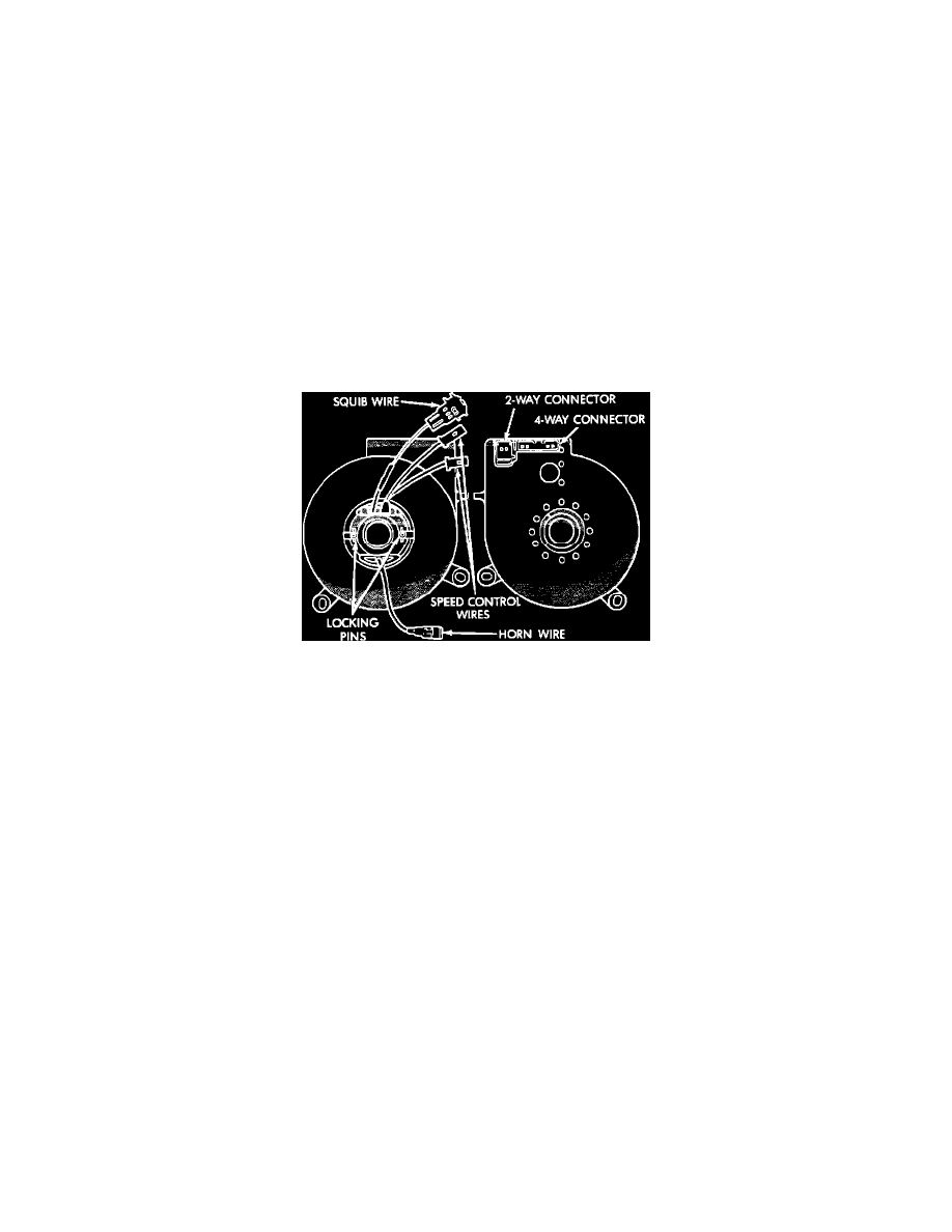
Fig. 171 Clock Spring
CENTERING
1. With clockspring removed, depress two plastic locking pins to disengage locking mechanism.
2. Keeping locking mechanism disengaged, rotate clockspring rotor clockwise to the end of its travel. Do not apply excessive torque.
3. From end of travel, rotate rotor 2 1/2 turns counterclockwise. At this position the horn wire should end up at the bottom and the squib wire at
the top. If not, rotate the rotor counterclockwise until the wires are properly positioned, but not more than 180° (1/2 turn).
4. Release pins and allow clockspring locking device to engage.
5. Install clock spring.
INSTALLATION
1. Ensure steering wheel is 180° (1/2 turn) to the right (clockwise) and is locked in place.
2. Ensure turn signal stalk in in the neutral position.
3. Install clockspring on steering shaft and push down on rotor until clockspring is fully seated on steering column.
4. Fasten clockspring to steering column using proper mounting bolts then torque bolts to 14-34 inch lbs. Tighten screw near ignition switch halo
light first.
5. Properly route clockspring harness then connect to instrument panel harness.
6. Ensure harness connectors are properly engaged.
7. Connect halo light and position wire on clockspring.
8. Install steering column shrouds and tilt lever.
9. Install steering wheel ensuring the flats on hub align with the clockspring. Pull yellow horn lead through smaller round hole and the airbag and
speed control through larger slot. Ensure wires do not get pinched under steering wheel.
10. Connect horn and airbag connectors to the airbag module.
11. Install the airbag module and torque bolts to 105-125 inch lbs.
12. Connect speed control and install switches then torque screws to 12-18 inch lbs.
13. Do not connect battery. Refer to Testing and Inspection/Procedures procedure.