
Concorde V6-201 3.3L VIN T MFI (1994)
Speed Control Servo: Testing and Inspection
Cruise Control Servo Test
1. Turn ignition switch to On position.
2. With speed control switch in On position, connect voltmeter negative lead to a chassis ground.
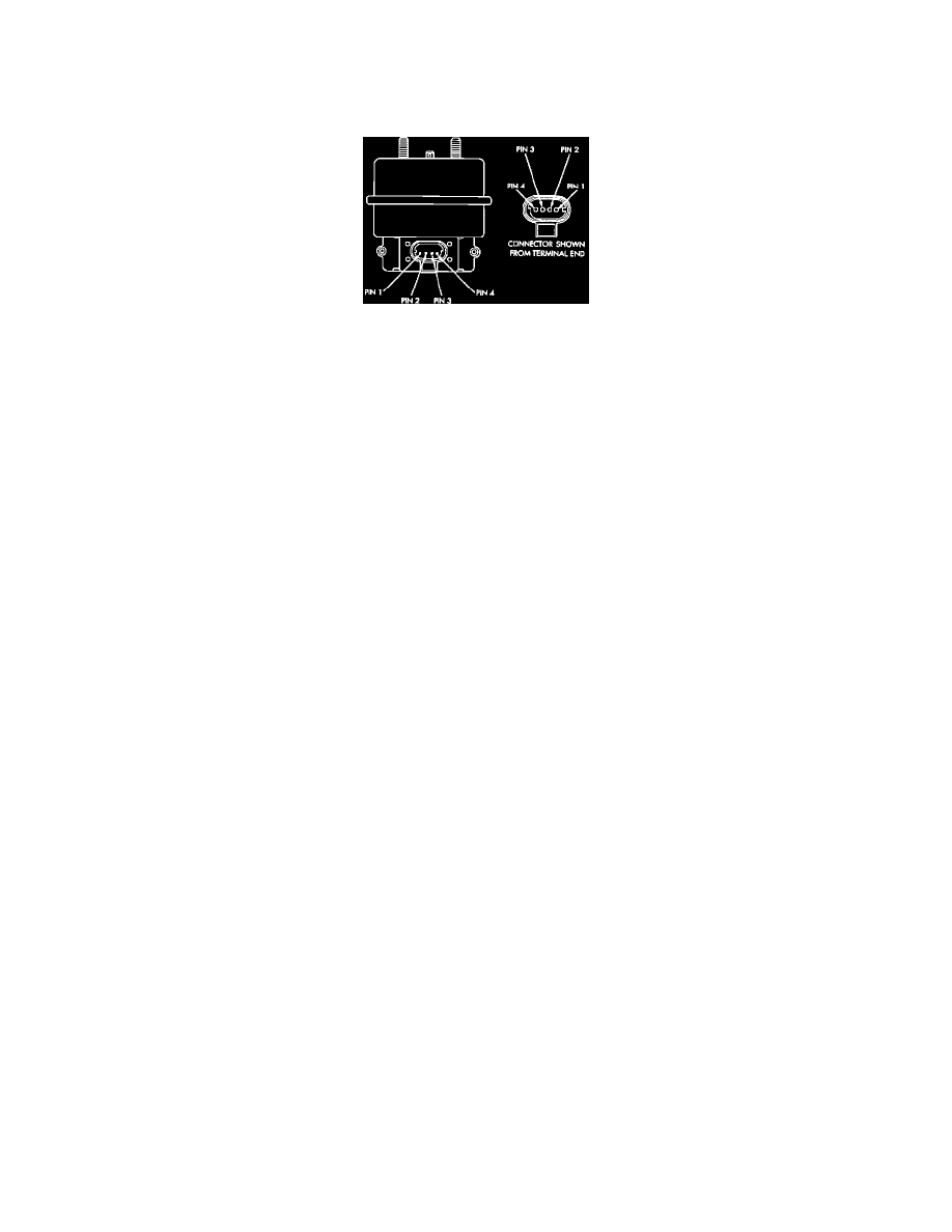
Fig. 72 Servo Harness Connector
3. Disconnect 4-way connector at servo.
4. If battery voltage is present at pin No. 2 proceed to step six, if battery voltage is not present at pin No. 2 of main harness 4-way connector, proceed
as follows:
a. Disconnect six way connector at stop lamp switch and test pin No. 1 of main harness for battery voltage, if voltage is present perform "Stop
Lamp Test".
b. If stop lamp switch test is satisfactory, repair wire between stop lamp switch and servo.
c. If no voltage at pin No. 1 of six way connector, remove ON/OFF speed control switch on steering wheel and disconnect two way connector.
Test pin No. 1 for battery voltage.
d. If voltage is present, perform "Speed Control Switch Test".
e. If speed control switch is satisfactory, check continuity across clockspring. If continuity exists, repair wire between stop lamp switch and
clockspring.
f.
If no voltage exists at pin No. 1 of both switches, test for battery voltage between ignition and the fuse, if satisfactory check fuse. If fuse is
satisfactory, repair wire between fuse and clockspring.
5. Connect a suitable jumper wire between pin No. 2 of 4-way connector and pin No. 2 of speed control servo.
6. In battery voltage is not present at remaining pin at servo, replace speed control servo.
7. Using suitable ohmmeter, connect negative lead to chassis ground and positive lead to pin 1 of 4-way connector.
8. If continuity does not exist, check and repair loose or damaged connectors or harness.