
Concorde V6-215 3.5L SOHC (1996)
Manifold Pressure/Vacuum Sensor: Testing and Inspection
Sensor Test
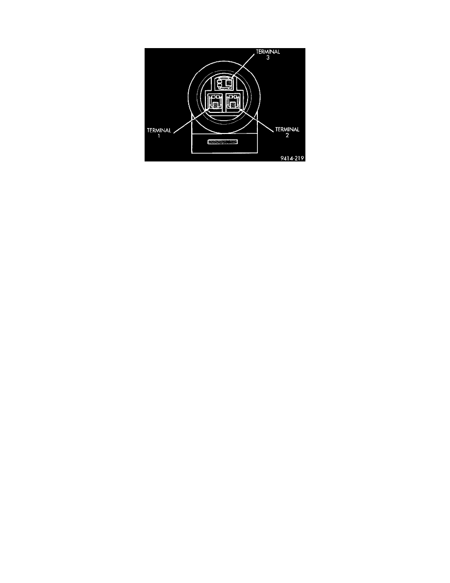
Fig. 60 MAP Sensor Connector
NOTE: To perform a complete test of MAP sensor and its circuitry, refer to appropriate Diagnostic Chart. To test the MAP sensor only, refer to the
following:
CAUTION: When testing the MAP sensor, be sure that the harness wires are not damaged by the test meter probes.
1. Test the MAP sensor output voltage at the MAP sensor connector between terminals 2 and 3 (Fig. 60).
-
With the ignition switch ON and the engine not running, output voltage should be 4 to 5 volts.
-
The voltage should drop to 1.5 to 2.1 volts with a hot, neutral idle speed condition.
-
If OK, go to next step. If not OK, go to step 3.
2. Test PCM terminal 36 for the same voltage described in the previous step to verify wire harness condition.
-
Repair as required.
3. Test the MAP sensor ground circuit at sensor connector terminal 1 and PCM terminal 43.
-
If OK, go to next step.
-
If not OK, repair as required.
4. Test MAP sensor supply voltage between sensor connector terminals 2 and 1 with the key ON.
-
The voltage should be approximately 5 volts (±0.5V).
-
Five volts (5 volts ±0.5V) should also be at terminal 61 of the PCM. If OK, replace MAP sensor.
-
If not OK, repair or replace the wire harness as required.