
Concorde V6-215 3.5L SOHC (1996)
16.
Install one of the 0-rings onto each end of the crossover tube (Figure 9).
17.
Install the crossover tube into the inlet and outlet rails (Figure 9). Secure the tube by installing the crossover tube clips.
18.
Install the inlet rail retainer and then slide the retainer toward the rear of the inlet rail (Figure 9).
19.
Remove the four (4) tie straps from the outlet rail reinforcements (if applicable).
20.
Install the outlet rail retainer and then slide the retainer toward the front of the outlet rail (Figure 9).
21.
Install the inlet and outlet rail retainer screws (Figure 9). Tighten the screws to 15 in-lbs (1.7 N.m).
22.
Install the six (6) fuel rail mounting bolts (Figure 9). Tighten the fuel rail mounting bolts to 100 in-lbs (11 N.m).
23.
Install the fuel tube support bracket bolt (Figure 9).
24.
Connect the negative battery cable.
25.
Using the DRB III, pressurize the fuel system and check for leaks.
26.
Connect the fuel pressure regulator vacuum hose.
27.
Connect the injector electrical connectors.
28.
Connect the coolant temperature sensor electrical connector.
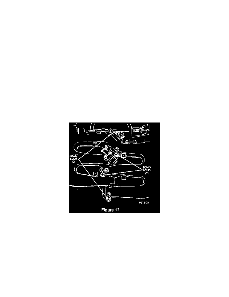
29.
Uncover the intake manifold openings and, using the supplied gasket, install the intake plenum. Tighten the mounting bolts to 250 in-lbs (28 N.m)
in the sequence shown in Figure 12.
30.
Install the air intake plenum support bracket bolt on each side of the manifold (Figure 6). Tighten the bolts to 250 in-lbs (28 N.m).
31.
Connect the EGR tube to the intake plenum (Figure 5) as follows:
a.
Loosely install the EGR tube using the supplied gaskets.
b.
Tighten the EGR tube screws to 200 in-lbs (22 N.m).
c.
Ensure that the insulation on the EGR tube aligns with and contacts the insulation on the vacuum harness at the rear of the engine.
32.
Connect the PCV hose, brake booster hose and other vacuum hoses to the intake plenum.
33.
Connect the purge hoses to both throttle bodies (Figure 4).