
Concorde V6-215 3.5L SOHC (1996)
Knock Sensor: Description and Operation
Knock Sensor Operation
PURPOSE
When a knock sensor detects a knock in one of the cylinders it sends a signal to the Powertrain Control Module (PCM). In response the PCM
retards the ignition timing by a predetermined amount.
THEORY/OPERATION
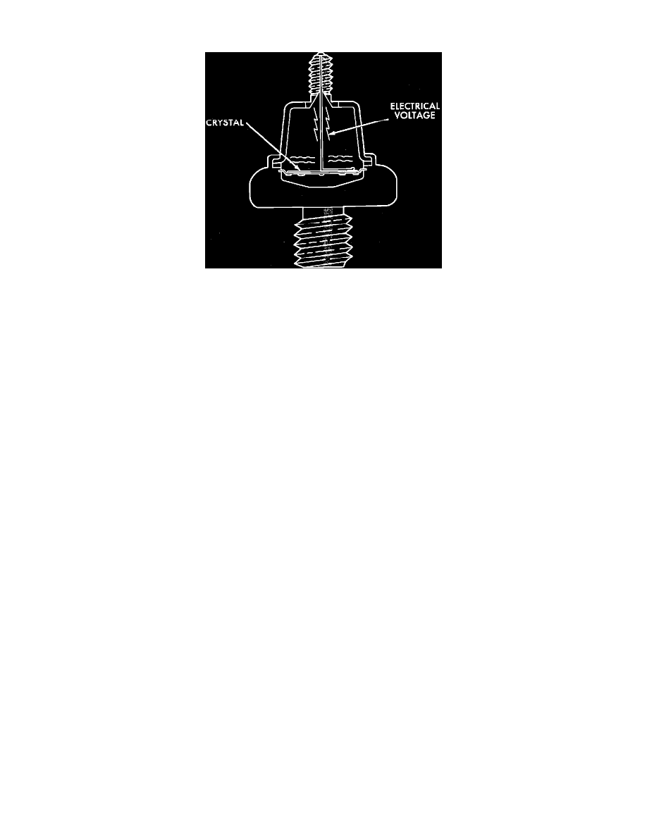
Knock sensors contain a crystal which constantly vibrates and sends a voltage signal to the PCM while the engine operates. When spark knock
occurs, the intensity of the crystals vibration increases, the knock sensor output voltage also increases signaling the PCM to retard ignition timing.
CIRCUIT OPERATION
It uses two knock sensors located on the top of the intake manifold. These sensors provide an input to the Powertrain Control Module (PCM) on
two circuits.
-
Circuit K42 is the input to the PCM for knock sensor #1.
-
Circuit K142 is the input to the PCM for knock sensor #2.
CIRCUIT OPERATION
The engine uses two knock sensors located on the top of the intake manifold which are case grounded. These sensors provide an input to the
Powertrain Control Module (PCM) on two circuits.
Circuit K42 is the input to the PCM for knock sensor #1 and connects to cavity 24 of the PCM connector.
Circuit K142 is the input to the PCM for knock sensor #2 and connects to cavity 25 of the PCM connector.