
Concorde V6-215 3.5L SOHC (1996)
Spindle: Service and Repair
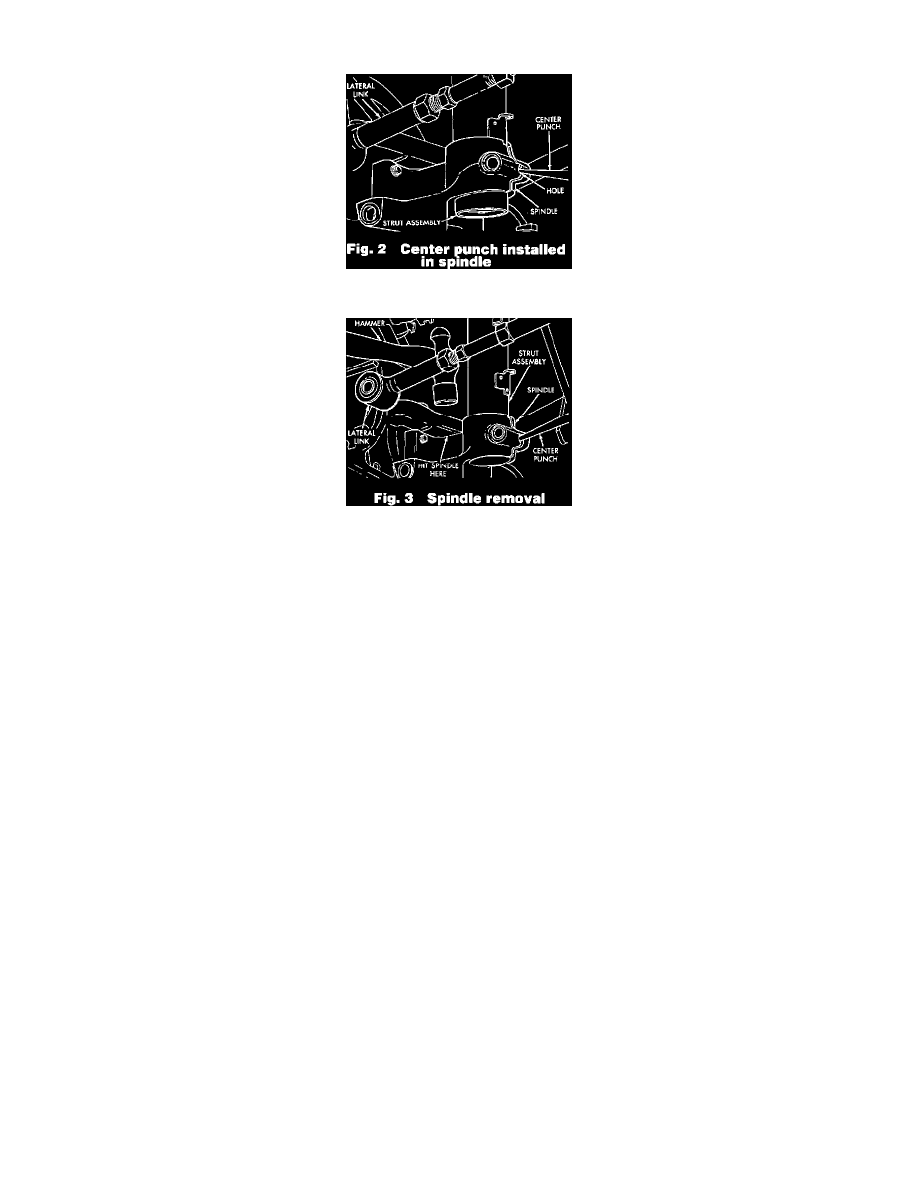
Fig. 2 Center Punch Installed In Spindle
Fig. 3 Spindle Removal
1, Raise and support vehicle then remove rear tire and wheel assemblies.
2. On models with rear disc brakes, proceed as follows:
a. Remove rear caliper assembly and support to frame using suitable wire.
b. Remove rear disc brake rotor.
3. On models with rear drum brakes, proceed as follows:
a. Remove brake flex hose bracket from support plate and wheel cylinder.
b. Remove brake drum.
4. On all models, remove rear hub and bearing assembly.
5. On models with drum brakes, remove rear brake support plate with parking brake cable attached.
6. On models with Anti-Lock Brake System (ABS), proceed as follows:
a. Remove speed sensor head from rear disc brake adapter.
b. Remove speed sensor cable routing tube from trailing arm.
7. On models with rear disc brakes, remove disc brake adapter, disc shield, park brake shoes and park brake cable as an assembly.
8. On all models, disconnect trailing arm from trailing arm bracket.
9. Disconnect lateral rod from spindle.
10. Loosen and remove rear spindle to strut assembly pinch bolt.
11. Tap a center punch into hole on spindle until punch is jammed into hole. Do not punch a hole in the strut with center punch.
12. Using a hammer, tap on on top surface of spindle, driving it down and off the strut assembly.
13. Remove spindle from vehicle.
14. Reverse procedure to install, noting the following:
a. Install spindle assembly onto bottom of strut assembly. Push or tap spindle assembly onto strut until notch in spindle is tightly seated against
locating tab on strut assembly.
b. Check rear toe as outlined under "Rear Wheel Alignment" in the "Wheel Alignment" unit repair section.