
Front Suspension Strut / Shock Absorber Repair | Concorde V6-32L (2000)
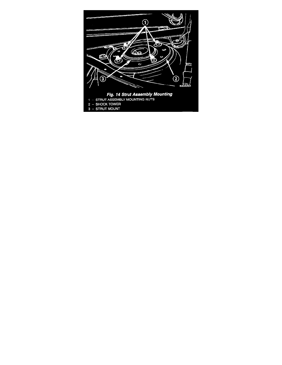
9. Remove the 4 strut assembly upper mount to strut tower mounting nut and washer assemblies.
10. Remove the strut assembly from the vehicle for inspection and disassembly. Refer to Disassembly and Assembly for the required procedure.
INSTALLATION
1. Install front strut assembly into shock tower. Install the 4 strut assembly upper mount to shock tower attaching nuts. Tighten the 4 strut mount to
strut tower attaching nuts to a torque of 37 Nm (28 ft. lbs.) torque.
2. Position steering knuckle into strut assembly.
CAUTION: The strut assembly to steering knuckle bolts are serrated were they go through strut assembly and steering knuckle. When installing bolts,
turn nuts onto bolts DO NOT TURN BOLTS IN STEERING KNUCKLE. If bolts are turned damage to steering knuckle will result.
3. Install the strut assembly to steering knuckle attaching bolts. Install nuts on attaching bolts. Tighten the strut assembly clevis to steering knuckle
attaching bolt nuts to a torque of 203 Nm (150 ft. lbs.).
4. Install braking disc back on front hub and bearing assembly. Install front brake caliper assembly on steering knuckle. Install the 2 caliper assembly
to steering knuckle attaching bolts. Tighten the caliper assembly guide pin bolts to a torque of 19 Nm (192 inch lbs.).
5. If the vehicle is equipped with antilock brakes. Install the front speed sensor cable routing bracket onto the front strut assembly.
6. Install outer tie rod on strut assembly. Install tie rod attaching nut. Tighten the tie rod attaching nut to a torque of 37 Nm (27 ft. lbs.).
7. Install stabilizer bar link on strut. Tighten the stabilizer link attaching nut to a torque of 95 Nm (70 ft. lbs.).
8. Install the wheel and tire assembly.
9. Tighten the wheel mounting nuts in proper sequence until all nuts are torqued to half specification. Then repeat the tightening sequence to the full
specified torque of 129 Nm (95 ft. lbs.).
10. Lower vehicle.
Disassembly and Assembly
OVERVIEW
The Strut assembly must be removed from the vehicle for it to be disassembled and assembled. Refer to Removal and Installation for the required
procedure.
For the disassembly and assembly of the strut assembly, use strut spring compressor, Pentastar Service Equipment (PSE) tool W-7200, or the equivalent,
to compress the coil spring. Follow the manufacturer's instructions closely.
DISASSEMBLY
1. If both struts are being serviced at the same time, mark the coil spring and strut assembly according to which side of the vehicle the strut was
removed from, and which strut the coil spring was removed from.